
Speed cooking oven with sloped oven floor and reversing gas flow
a technology of oven floor and oven floor, which is applied in the direction of furnaces, heating types, stoves or ranges, etc., can solve the problems of non-uniform energy fluxes between the top and bottom of food, requiring complex control of microwave and convection heating system, and achieving high speed with quality requires a fairly complex and expensive variable speed convection blower motor control and electronic oven control, etc., to achieve the effect of reducing grease entrainment and high heat transfer ra
- Summary
- Abstract
- Description
- Claims
- Application Information
AI Technical Summary
Benefits of technology
Problems solved by technology
Method used
Image

Examples
Embodiment Construction
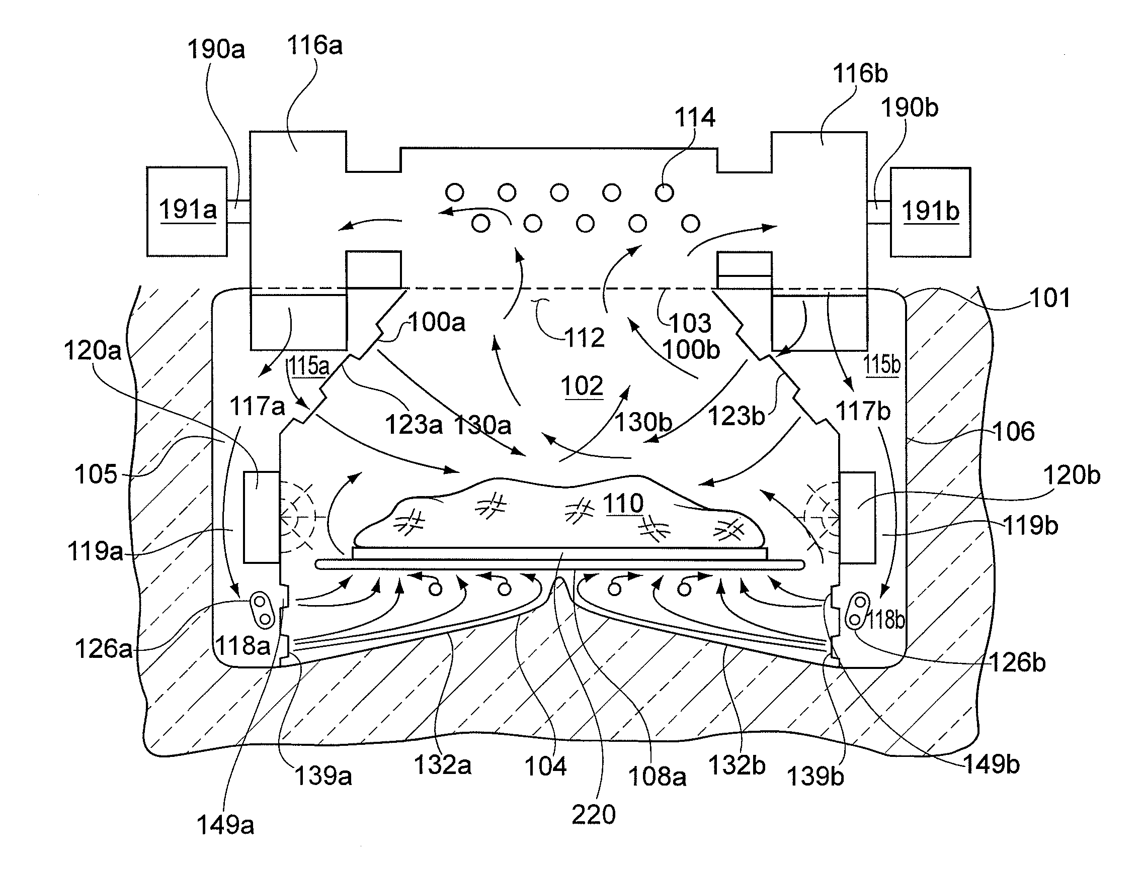
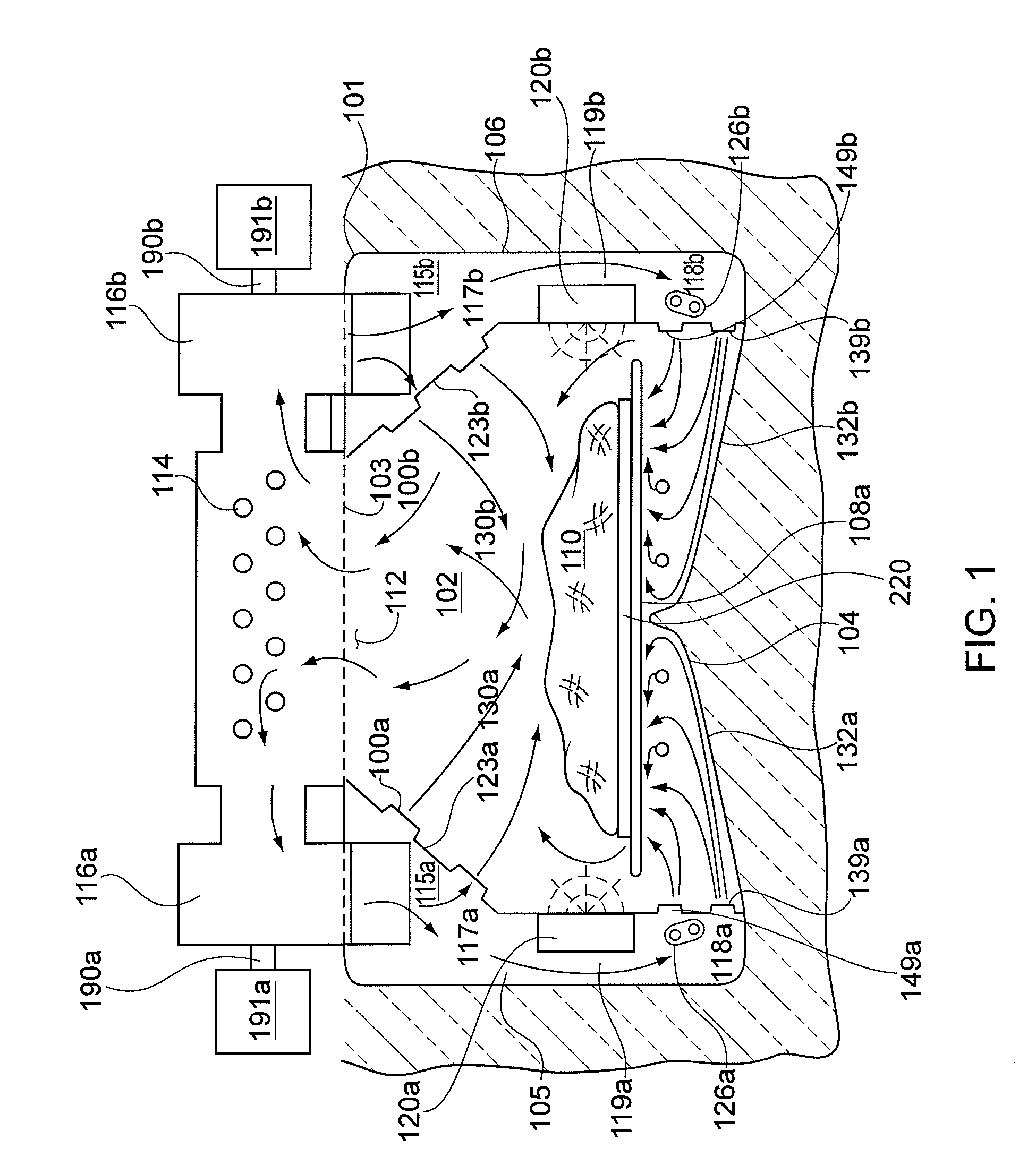
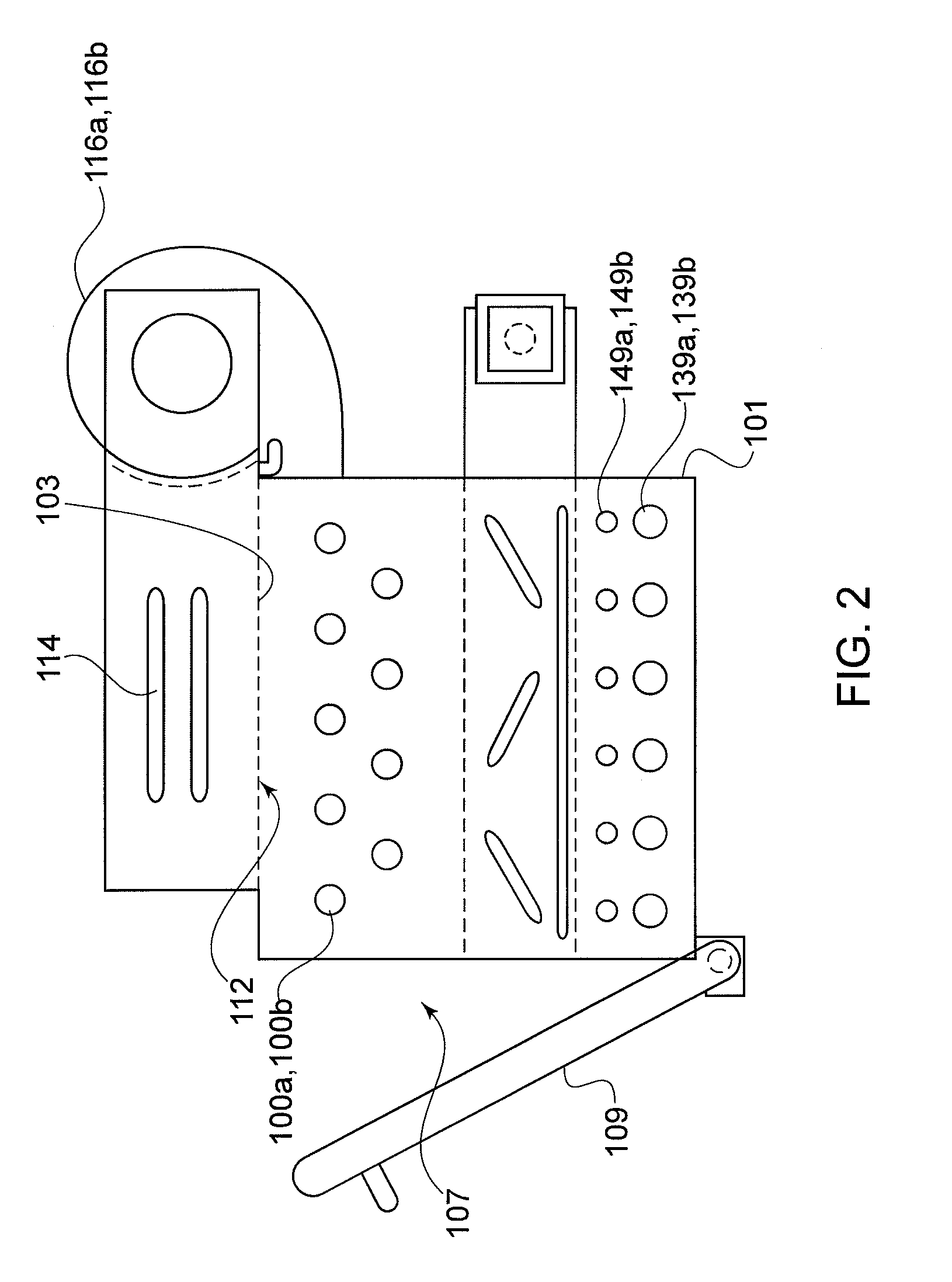
[0022] An exemplary version of the speed cook oven with sloped floor and reversing gas flow is shown in FIGS. 1-2. Appliance 101 includes an oven cavity 102 generally defined by a top wall 103, a bottom wall 104 which angles or slopes up from the side walls upward to the centerline of oven cavity 102 (providing bottom side primary gas flow directional control and enabling very turbulent flow on the bottom side of the food product), left side wall 105, right side wall 106, a back wall 194 and a front wall 195. Oven cavity 102 also has associated therewith an access opening 107 through which food items 110 may be placed within oven cavity 102 upon cooking rack 108a, FIG. 1 or within cooking pan or vessel 220, FIG. 1. Cooking appliance 101 has a hinged door 109 pivotally attached to the oven front for closing the cooking section opening 107 during cooking operation. Hinged door 109 may be swung between an open position wherein the door allows access to oven cavity 102 and a closed posi...
PUM
 Abstract
Description
Claims
Application Information