Speed cooking oven with sloped oven floor and reversing gas flow

a technology of oven floor and oven floor, which is applied in the direction of furnaces, heating types, stoves or ranges, etc., can solve the problems of non-uniform energy fluxes between the top and bottom of food, requiring complex control of microwave and convection heating system, and achieving high speed with quality requires a fairly complex and expensive variable speed convection blower motor control and electronic oven control, etc., to achieve the effect of reducing grease entrainment and high heat transfer ra

Active Publication Date: 2011-09-06
TURBOCHEF TECH INC
View PDF114 Cites 94 Cited by
  • Summary
  • Abstract
  • Description
  • Claims
  • Application Information

AI Technical Summary

Benefits of technology

[0018]The invention relates to a single rack cook (slot oven) bottom side convection flow (relative to the food) method that overcomes issues associated with the impingement style microwave / convection ovens while still maintaining single rack cooking speeds greater than 5 times. Improvements described in this invention include: (1) a bottom side (relative to the food product) reversing gas flow that tends to average flow conditions across the bottom of a food product or container holding a food product while providing high heat transfer rates for rapid cooking; (2) an oven cavity floor that is continuous and not interrupted by air ducts or microwave feeds; (3) a means to control or enhance bottom side (relative to the food) airflow / heat transfer using smaller air flows to direct the primary bottom side cooking airflows rather than mechanical means; (4) providing a bottom side flow field where grease entrainment is reduced by eliminating the vertical impingement style flow that tends to throw or kick grease into the air stream from both the pan and food product.

Problems solved by technology

While this approach produces very high speed cooking (5-10 times faster than conventional oven technology) with high quality, it has the many limitations including non-uniform energy fluxes (convection and microwave) between the top and bottom of the food that requires complex control of the microwave and convection heating system to achieve rapid high quality cooking.
Achieving high speed with quality requires a fairly complex and expensive variable speed convection blower motor control and electronic oven controls.
Lack of independent top and bottom convection (browning) heating given top impingement flow must wrap around food product and flow under the product needed for bottom side heating.
This requires use of an expensive and fragile ceramic platter that is transparent to microwave as well as configured with a flow channels needed for bottom side browning.
Given the very rapid circulation of air through the oven (high velocity impingement), the ovens are noisy.
Uniform vertical jet flow fields over a range of flow rates needed for cooking are difficult to achieve over the cooking rack area.
A common outcome of this lack of uniformity is to restrict or reduce the cook zone to that area that experiences relative to rack which reduces the cooking capacity for a given cavity size or requires a larger oven.
Using rotation to compensate for jet non-uniformity also reduces the useful cooking area of the appliance by at least 25%.
Some designs further complicate the ability to achieve a uniform flow conditions by having the vertical jet flow pattern coupled to the ceramic platter used to channel flow under the food.
Their construction is complex given the need to add or modify the oven cavity roof for impingement nozzle plates / supply ducts, the bottom for microwave launching, and the back wall for ducts / catalysts and blower hardware.
Additionally, it is difficult to maintain a microwave seal to the cavity floor (microwave launches through the oven floor) to prevent grease / liquid contamination of the wave guides
Grease control given the high velocity of the impinging jets tend to entrain a great deal of grease (particles and vapor) into the convection air which quickly soils the oven cavity surfaces and requires a large catalyst (cost and pressure drop requiring a bigger blower) to control the airborne grease
This approach has several problems such as the oven floor located air nozzle plate and its supply duct are very difficult to maintain given their susceptibility to food spoils and grease accumulation.
This adds complexity to the airflow system.
It also makes uniform jet fields difficult to achieve at flows other than the design flow rates which are needed when food products that need a less aggressive airflow are baked.
Such non-uniform flows will reduce to the cook area to a region where a reasonable flow field exits to cook to a good quality or will require that the convection flows be greatly reduced resulting in longer cook times.
The general oven construction is complex as the supply duct to the roof air plate must also act as a launch box for the microwaves.
The floor ducts may become complex part if they are designed to be removed for cleaning / servicing.
The nature of having supply ducts on the floor and roof of the oven greatly reduced the useful volume (cook chamber) of the oven as much as half of the height of the cavity is occupied by these air channels.
These designs in general have a number of limitations.
Microwave launch method cannot equally illuminate multiple racks or pans of food and as a result, the microwave energy is necessarily limited in order to avoid hot spots and poor quality cooking.
In addition to the microwave non-uniformity's, the convection air flow also has non-uniform behavior.
This results in lower airflow rates in the oven limiting the convection heat transfer rate and hence limits the cooking speed of the oven.
This creates flow non-uniformity's from the center rack position to the top / bottom positions.
Balancing the flow over several pans is difficult as the air is drawn to the center of the back wall.
As discussed above, imparting high flows to the oven in order to achieve high cook speeds results in non-uniform cooking.
The effectiveness of this approach is limited and in general the oven airflow rates are maintained at modest flows.
In addition to the above mentioned issues relative to cooking speeds, these oven designs do not manage or handle airborne grease entrained by the convection air.

Method used


Image

  • Speed cooking oven with sloped oven floor and reversing gas flow
  • Speed cooking oven with sloped oven floor and reversing gas flow
  • Speed cooking oven with sloped oven floor and reversing gas flow

Examples


Embodiment Construction

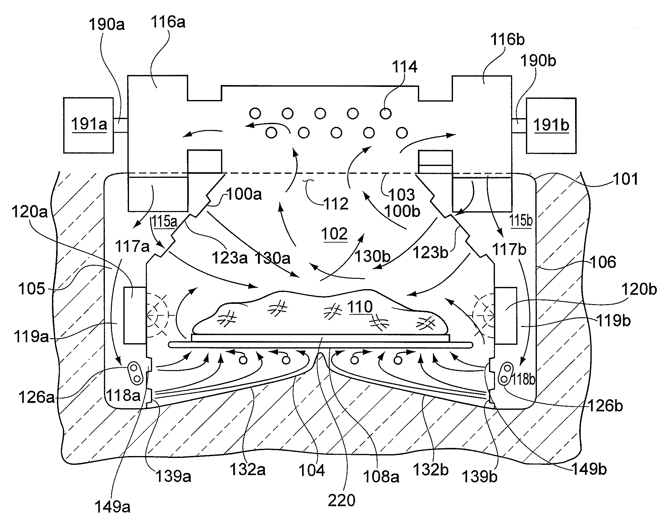
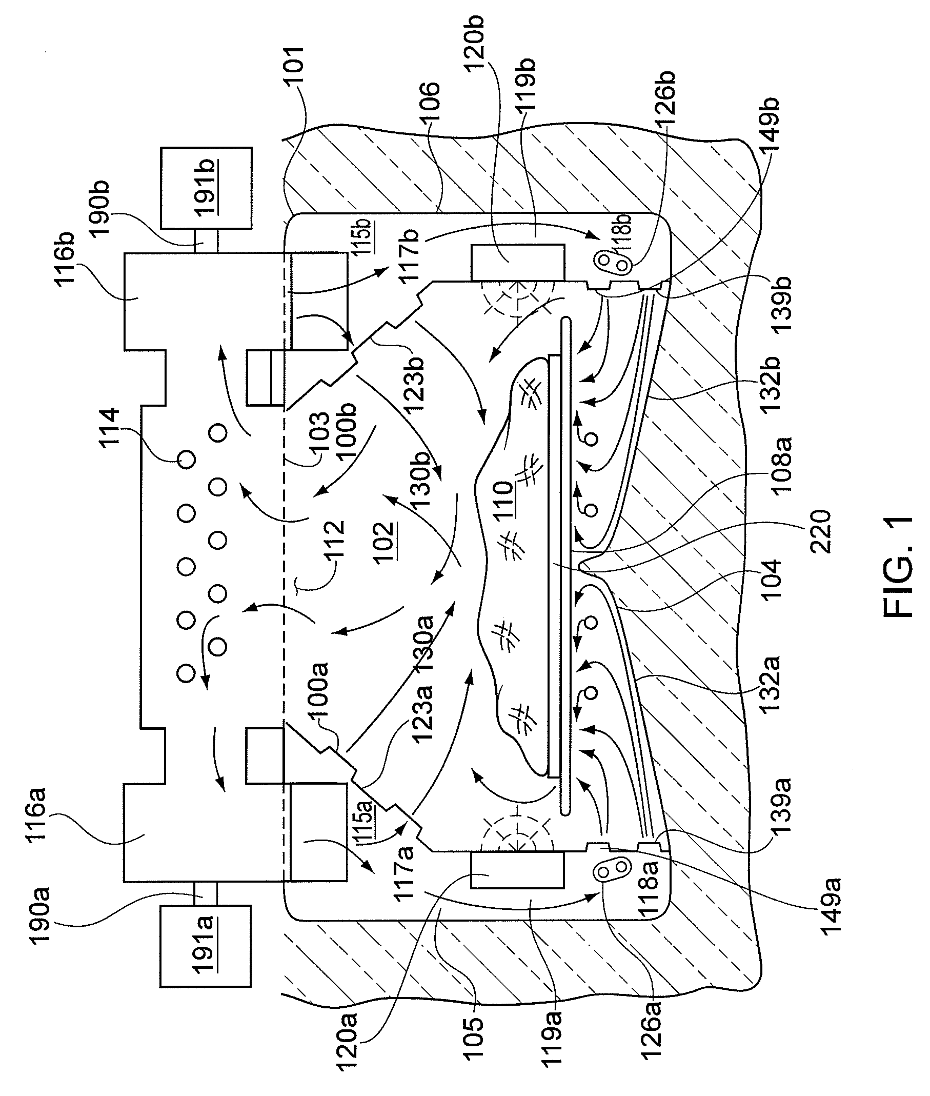
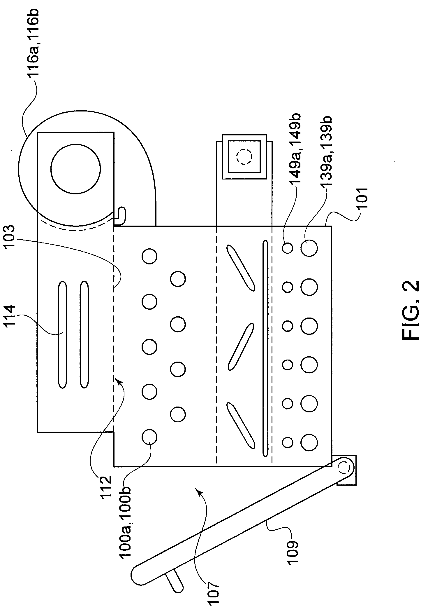
[0022]An exemplary version of the speed cook oven with sloped floor and reversing gas flow is shown in FIGS. 1-2. Appliance 101 includes an oven cavity 102 generally defined by a top wall 103, a bottom wall 104 which angles or slopes up from the side walls upward to the centerline of oven cavity 102 (providing bottom side primary gas flow directional control and enabling very turbulent flow on the bottom side of the food product), left side wall 105, right side wall 106, a back wall 194 and a front wall 195. Oven cavity 102 also has associated therewith an access opening 107 through which food items 110 may be placed within oven cavity 102 upon cooking rack 108a, FIG. 1 or within cooking pan or vessel 220, FIG. 1. Cooking appliance 101 has a hinged door 109 pivotally attached to the oven front for closing the cooking section opening 107 during cooking operation. Hinged door 109 may be swung between an open position wherein the door allows access to oven cavity 102 and a closed posit...


PUM


Abstract

A speed cooking oven with sloped oven floor and reversing gas flow is disclosed comprising a cooking cavity, a controller, thermal heating source, blower assembly, air directing means, and a sloped oven floor that directs air flow from the oven side walls to oven center thereby producing a highly turbulent reversed air flow.

Description

CROSS REFERENCE TO RELATED APPLICATIONS[0001]The present application claims priority to International Application No. PCT / US2005 / 035605 filed 5 Oct. 2005; claims priority to U.S. application Ser. No. 11 / 098,280 filed 4 Apr. 2005; claims priority to International Application No. PCT / US2006 / 009075 filed 14 Mar. 2006 and claims priority to U.S. application Ser. No. 11 / 392,050 filed 29 Mar. 2006. Upon entry into the National Stage in the United States of America, the present application will be a continuation-in-part of U.S. application Ser. No. 11 / 098,280 filed 4 Apr. 2005; will be a continuation-in-part of U.S. application Ser. No. 10 / 614,268 filed 7 Jul. 2003; will be a continuation-in-part of U.S. application Ser. No. 10 / 614,532 filed 7 Jul. 2003; and will be a continuation-in-part of U.S. application Ser. No. 11 / 392,050 filed 29 Mar. 2006.[0002]The present application contains technical disclosure in common with International Application No. PCT / US2003 / 021225 filed 5 Jul. 2003; con...

Claims


Application Information

Patent Timeline
Patent Type & Authority Patents(United States)
IPC IPC(8): A47J37/00H05B6/80F24C15/32
CPCA21B1/245F24C15/325H05B6/6473H05B6/6485A47J39/003A47J37/0641A47J37/0647A21B1/24A21B1/36A21B1/00F24C15/32
Inventor MCFADDEN, DAVID H.BOLTON, DAVID A.
Owner TURBOCHEF TECH INC
Why Eureka
Try Eureka