Apparatus and method for forming internally ribbed or rifled tubes

Active Publication Date: 2005-10-20
DOOSAN BABCOCK ENERGY AMERICA
View PDF26 Cites 17 Cited by
  • Summary
  • Abstract
  • Description
  • Claims
  • Application Information

AI Technical Summary

Benefits of technology

[0013] The present invention overcomes the disadvantages of prior apparatus and methods for forming internally helically or spirally ribbed or rifled tubes. The apparatus and method of the present invention increase productivity and prolong tool life in a cold drawing process for forming internal helical or spiral ribs or rifles in tubing. With the present invention, the forces exerted on the plug tool used to form internal helical or spiral ribs or rifles in tubing in a

Problems solved by technology

The use of internally ribbed tubes was still limited because the benefit derived from the internally ribbed tubes was not as great in many boiling ranges with certain arrangements and dimensions of the ribs.
To date, however, it has not allowed sufficient reduction to enable a once-through boiler furnace to be cooled successfully in a single vertical pass.
The introduction of “optimized” multi-lead rifled tubing with steeper lead angle and taller rib, as represented by Kastner et al ('194), has finally achieved this goal but the manufacturing difficulties have been such that it could not be economically produced in commercial quantities.
Small lengths of rifled tubing produced for performance testing purposes do not reveal the range of problems associated with the manufacture of rifled tubing in commercial quantities.
Production of internally ribbed tubes pursuant to the Kastner et al. patent

Method used


Image

  • Apparatus and method for forming internally ribbed or rifled tubes
  • Apparatus and method for forming internally ribbed or rifled tubes
  • Apparatus and method for forming internally ribbed or rifled tubes

Examples


Embodiment Construction

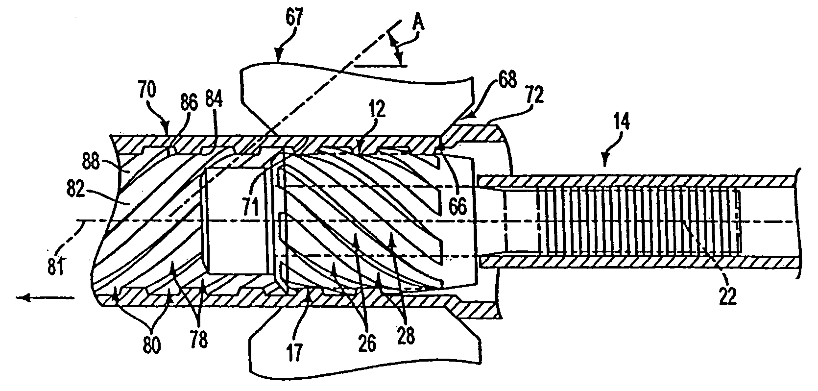
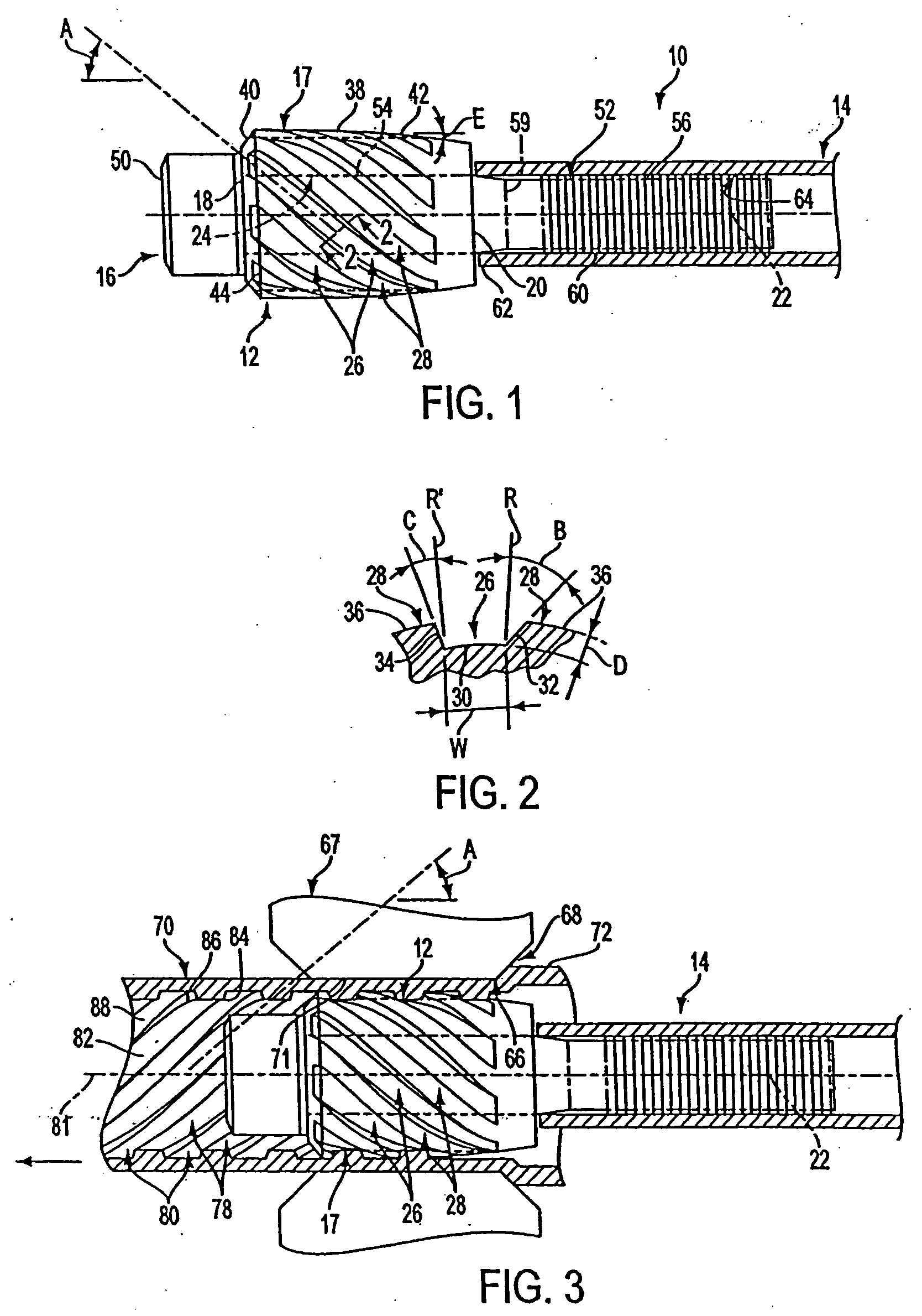
[0030] A plug tool 10 according to the present invention is depicted in FIG. 1 and comprises a drawing plug 12 assembled to a shaft 14 via a connector 16. The plug 12 has a plug body 17 with a forward end 18, a rearward end 20, a central longitudinal axis 22 and a bore 24 extending therethrough coaxial with the central longitudinal axis 22. The plug 12 is formed with a plurality of external grooves 26 extending longitudinally along the plug at a helix angle A to the central longitudinal axis 22. The grooves 26 are disposed at equally spaced locations about the central longitudinal axis 22 in alternating arrangement with external lands 28, with each groove 26 being disposed between a pair of adjacent lands 28. As shown in cross-section normal to a groove 26 in FIG. 2, each groove 26 comprises a root surface 30 and a pair of flank surfaces 32 and 34 extending angularly outwardly from the root surface 30 to land surfaces 36 of the adjacent lands 28, respectively. The root surface 30 is...


PUM

PropertyMeasurementUnit
Angleaaaaaaaaaa
Angleaaaaaaaaaa
Angleaaaaaaaaaa

Abstract

A plug tool for forming internally helically ribbed tube comprises a plug body for being rotatably disposed in a die orifice of a drawing die. The plug body has a central longitudinal axis, a plurality of external grooves equally spaced about the axis and a plurality of external lands in alternating arrangement with the grooves. The grooves extend along the plug body at a helix angle to the axis. Each groove has a normal cross-section defined by a root surface and opposing flank surfaces extending angularly outwardly from the root surface to adjacent land surfaces. The flank surfaces extend angularly outwardly from the root surface in opposite directions at different angles from one another. A method for forming internally helically ribbed tube involves drawing a length of tubing over the plug body rotatably disposed in a die orifice of a drawing die and constricting the tubing in the drawing die to force the tubing into the grooves of the plug body to form a plurality of internal helical ribs in the tubing in correspondence to the grooves.

Description

BACKGROUND OF THE INVENTION [0001] 1. Field of the Invention [0002] The present invention relates generally to the formation of internally ribbed or rifled tubes and, more particularly, to plug tools for forming internal helical or spiral ribs in tubing, and to methods of producing internally helically or spirally ribbed or rifled tubes. [0003] 2. Brief Discussion of the Related Art [0004] Internally ribbed or rifled tubes are used for various heat transfer or heat exchange applications including steam generating and superheating equipment such as boilers. Internally ribbed or rifled tubes present various advantages over plain bore tubes including the ability to sustain high heat transfer rates at higher pressures, higher enthalpies and lower mass fluxes than plain bore tubes. [0005] The advantage of using internally ribbed or rifled tubes in furnaces of boilers was recognized during the development of steam boilers. Initially, however, internally ribbed tubes were lap-welded tubes....

Claims


Application Information

Patent Timeline
IPC IPC(8): B21C1/24B21C3/16B21C37/20
CPCB21C1/24B21C37/207B21C3/16
Inventor JESSON, JOHN E.SMITH, MICHAEL J.
Owner DOOSAN BABCOCK ENERGY AMERICA
Why Eureka
Try Eureka