

Biomass pyrolysis in refinery feedstock
a biomass pyrolysis and feedstock technology, applied in the field of pyrolysis, can solve the problems of difficult to achieve good heat transfer on both sides of the heat exchange surface, difficult to provide enough heat with reasonable gas flow-rate, and difficult to scale up methods, etc., to achieve easy admixture, improve pyrolysis, and improve cost and efficiency
Active Publication Date: 2011-07-28
PHILLIPS 66 CO
View PDF8 Cites 18 Cited by
- Summary
- Abstract
- Description
- Claims
- Application Information
AI Technical Summary
Benefits of technology
[0013]The invention relates to an improved method of biomass pyrolysis, wherein the heat source is a hot petroleum feedstock, which provides heat and may also contribute organic material to the pyrolysis reaction. Biomass pyrolysis in a petroleum feedstock, such as vacuum gas oil (VGO), rather than with a solid heat source such as sand or salt, improves pyrolysis because the hot hydrocarbon liquid is readily available from other processes, thus improving cost and efficiency, is easily admixed with the biomass, and provides very high heat transfer rates and 100% conversion. It also simplifies the mechanics of the operation, since existing plumbing and fixtures will suffice to deliver and mix the hot petroleum feedstock with the biomass particles.
[0015]The advantage of this process is that it utilizes an organic (a hydrocarbon or “HC” base) liquid media to achieve heat transfer. The invention improves heat transfer to the biomass particle resulting in improved product yield, and the resulting bio-oil is of higher quality due to thermochemical interaction with the hot petroleum feedstock. The reaction temperature may also be decreased significantly from common fast pyrolysis temperatures (500° C.), thus further improving efficiencies and cost.
Problems solved by technology
Direct heat transfer with a hot gas (which can be recycled) is possible in a pyrolysis reactor, but it is difficult to provide enough heat with reasonable gas flow-rates due to the low specific heat of a relatively thin gas.
Indirect heat transfer with exchange surfaces (such as vessel walls) is also possible, but it is difficult to achieve good heat transfer on both sides of the heat exchange surface, and these methods are not easily scaled up.
This is an effective method, but the technology for moving, recovering, and reheating the solid can be complex.
However, the sand must be reheated in a separate vessel, and mechanical reliability is a concern.
Thus, there has been no large-scale commercial implementation of the auger technology.
Like other shallow transported-bed reactors, relatively fine particles are required to obtain a good liquid yield, and there have been no large scale commercial implementation of this technology.
There is some ablation by attrition with the sand particles, but it is not as effective as in the ablative processes (not described herein).
There is some dilution of the products, which makes it more difficult to condense and then remove the bio-oil mist from the gas exiting the condensers.
The main challenges have been in improving the quality and consistency of the bio-oil, but this process has been scaled up by companies such as Dynamotive and Agri-Therm.
Although this process can be scaled up, it is rather complex and the products are much diluted, which greatly complicates the recovery of the liquid products.
Method used
View moreImage
Smart ImageViewing Examples

Examples
example 1
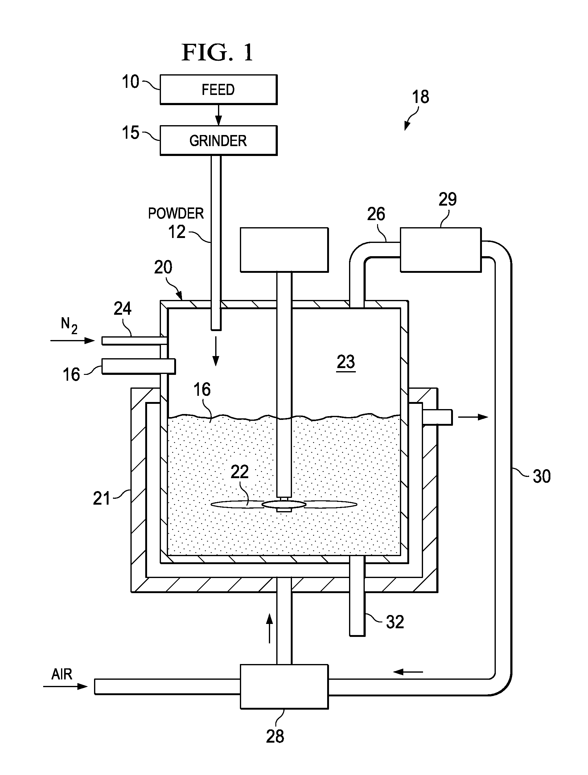
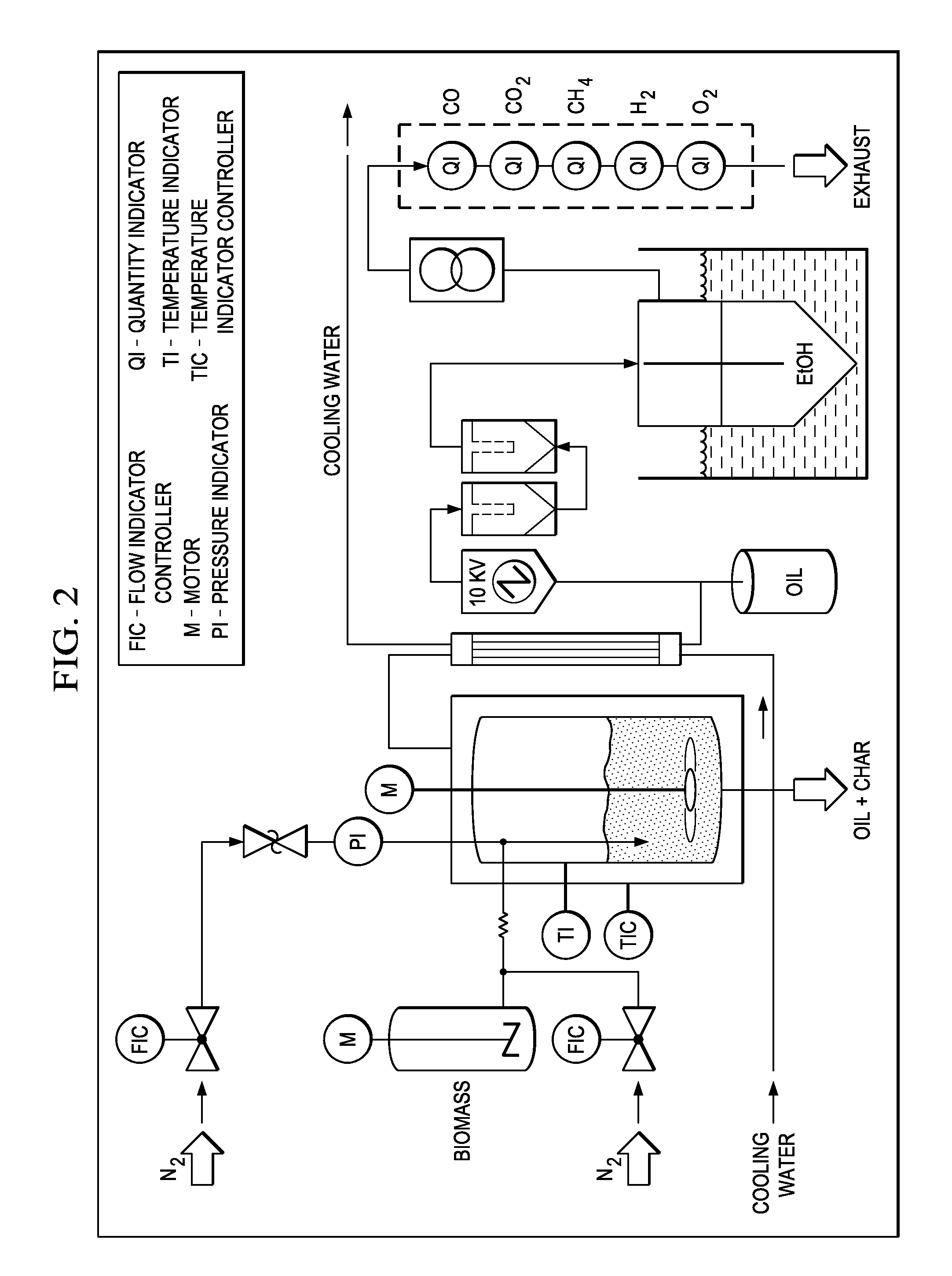
[0032]FIG. 2 is an embodiment of a laboratory scale biomass pyrolysis reactor used in this Example. The biomass pyrolysis reactor was electrically heated and had a condenser train after the reactor.
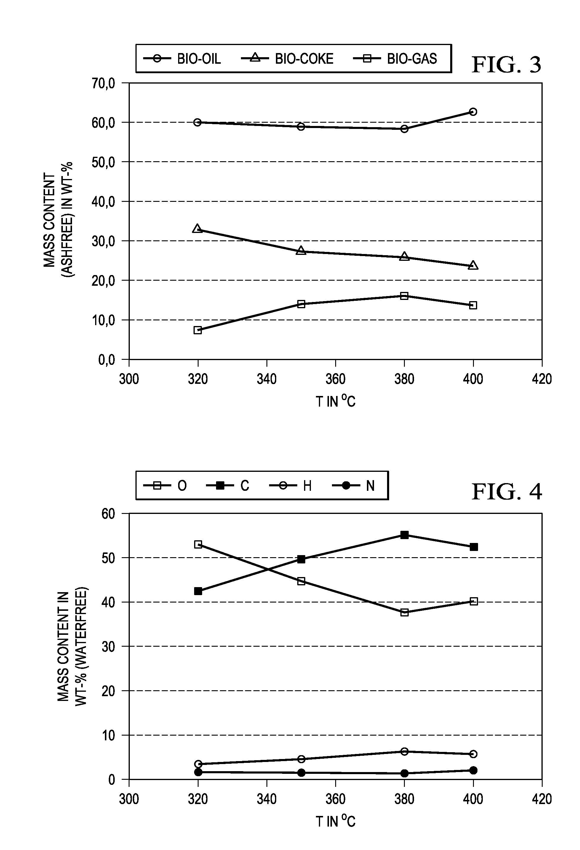
[0033]With switch grass as the biomass and VGO as the refinery feedstock, experiments were performed at temperatures of about 320° C., about 350° C., about 380° C. and about 400° C. The average biomass feed rate was about 217 g / h with a nitrogen flow rate of about 50 l / h. The refinery feedstock was fed into a conveyor tube at a flow of about 15 l / h. The experiments lasted typically from about 1 to about 2 hours. FIG. 3 is a chart for the product distribution and FIG. 4 is an elementary analysis of the bio-oil.
Login to View More PUM
| Property | Measurement | Unit |
|---|---|---|
| temperature | aaaaa | aaaaa |
| size | aaaaa | aaaaa |
| temperatures | aaaaa | aaaaa |
Abstract
This invention relates to biomass pyrolysis through the use of a hot liquid refinery feedstock as a heat transfer medium, preferably a vacuum gas oil feedstock.
Description
CROSS REFERENCE TO RELATED APPLICATIONS[0001]This application claims priority to 61 / 299,906, filed Jan. 29, 2010, and incorporated herein in its entirety.FEDERALLY SPONSORED RESEARCH STATEMENT[0002]Not applicable.REFERENCE TO MICROFICHE APPENDIX[0003]Not applicable.FIELD OF THE INVENTION[0004]This invention relates to pyrolysis, and more particularly to a method for pyrolytically processing biomass material into useful byproducts through the use of a refinery feedstock as a heat transfer medium and / or source of hydrogen for hydrodeoxygenation.BACKGROUND OF THE INVENTION[0005]Pyrolysis is the chemical decomposition of a condensed substance by heating. The word is coined from the Greek-derived elements pyro—meaning “fire”—and lysis—meaning “decomposition.” Pyrolysis is a special case of thermolysis, and is most commonly used for organic materials. It occurs spontaneously at high temperatures (above 300° C. for wood), for example in wildfires or when vegetation comes into contact with ...
Claims
Login to View More Application Information
Patent Timeline
 Patent Type & AuthorityApplications(United States)
IPC IPC(8): C10G1/00
CPCC10G1/02C10G3/40C10G2300/4006C10G2300/1074C10G2300/1011Y02P30/20
InventorJESS, ANDREASKAUFMANN, DOMINICDAUGAARD, DAREN E.
OwnerPHILLIPS 66 CO