Plasmapheresis centrifuge bowl

a centrifuge and plasmapheresis technology, applied in the direction of centrifuges, packaging foodstuffs, packaging, etc., can solve the problems of inconvenient manufacturing of the upper cover by the above process, complicated manufacturing and related costs, and certain inconvenience, so as to reduce heat

Inactive Publication Date: 2006-09-07
JUAN TIEN CHU
View PDF32 Cites 15 Cited by
  • Summary
  • Abstract
  • Description
  • Claims
  • Application Information

AI Technical Summary

Benefits of technology

[0009] In order to solve the drawbacks and inconvenience in the prior art, the object of the present invention is to provide a rotary sealing assembly for a plasmapheresis centrifuge bowl, whereby to reduce the heat generated by the rotating friction of the centrifuge bowl conducting into the blood within the centrifuge bowl.

Problems solved by technology

Further, the conventional centrifuge bowl is formed by manufacturing individual parts and adhering them one by one, which causes a very complicated procedure in manufacturing and the related cost.
It is inconvenient to manufacture the upper cover by the above process.
Further, after being adhered, the upper cover cannot be opened any more, which also causes a certain degree of inconvenience.

Method used


Image

  • Plasmapheresis centrifuge bowl
  • Plasmapheresis centrifuge bowl
  • Plasmapheresis centrifuge bowl

Examples


Embodiment Construction

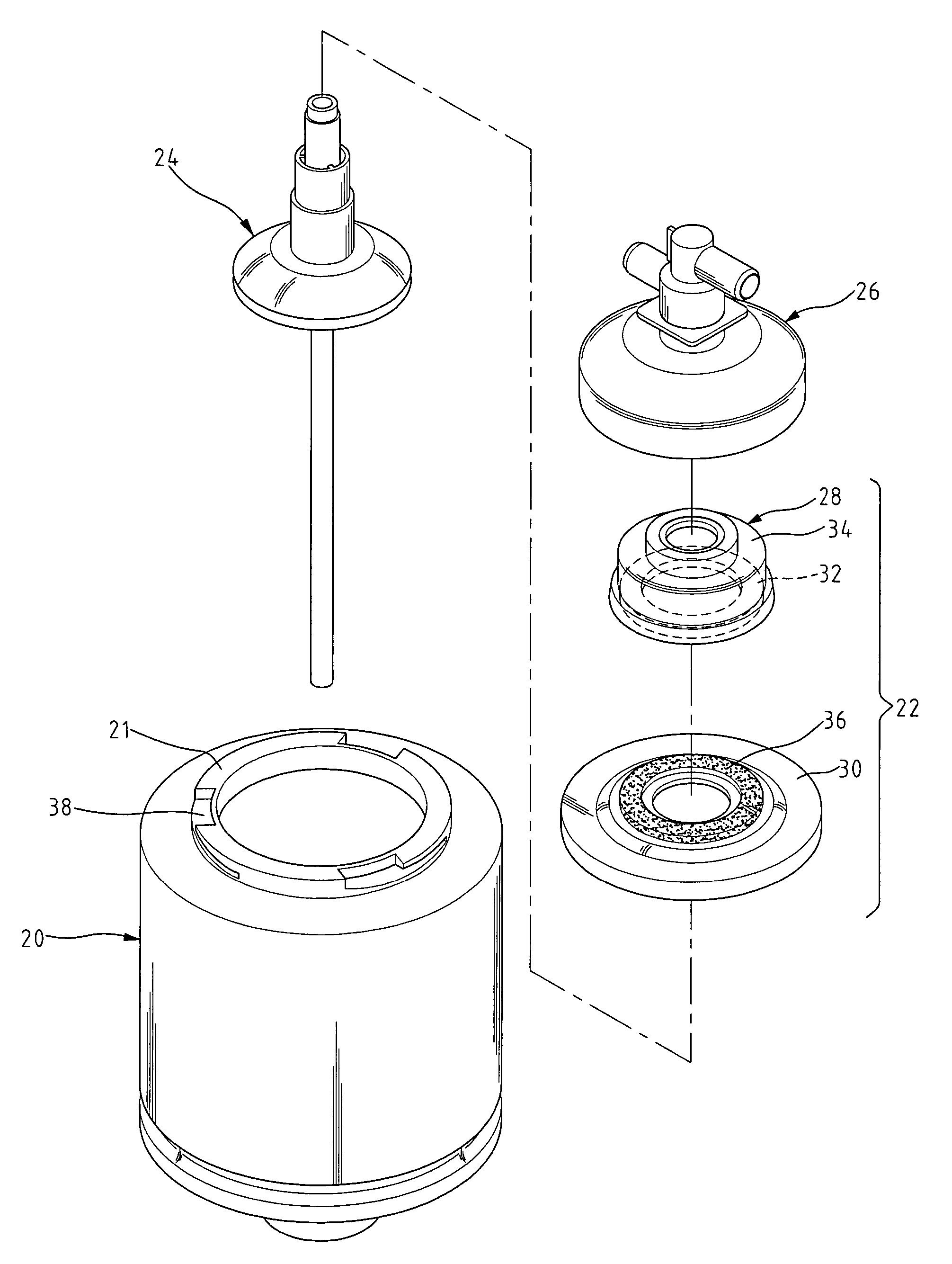
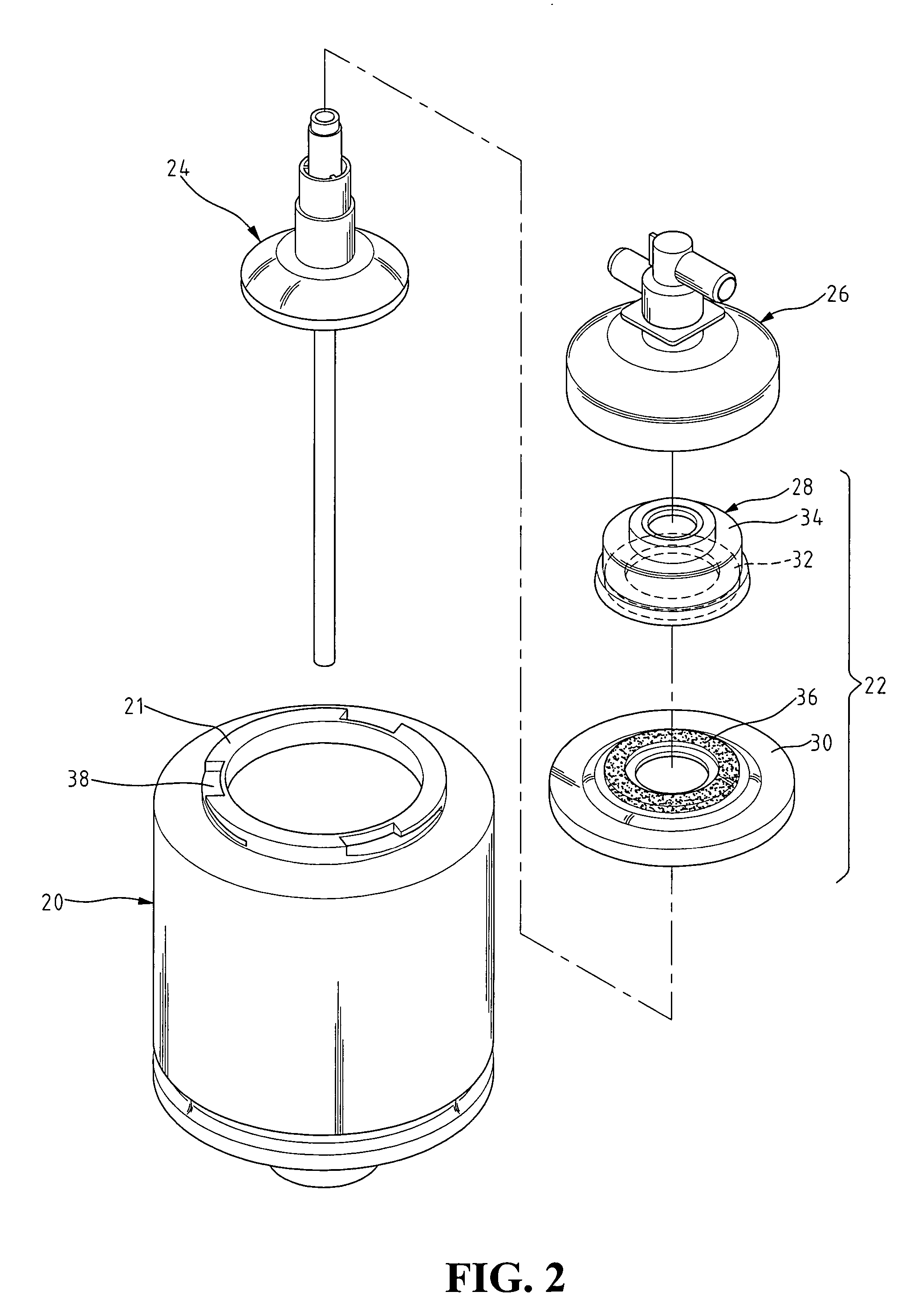
[0024]FIG. 2 is an exploded perspective view of the plasmapheresis centrifuge bowl of the present invention. The plasmapheresis centrifuge bowl 2 of the present invention comprises a plasmapheresis centrifuge bowl body 20, a ring-shaped dynamic sealing assembly 22 movably locked on the bowl mouth 21 of the plasmapheresis centrifuge bowl body 20, an integrated draining pipe assembly 24 provided below the ring-shaped dynamic sealing assembly 22 and partially penetrating through the ring-shaped dynamic sealing assembly 22, and a head assembly 26 mounted on the ring-shaped dynamic sealing assembly 22 and snapped on the integrated draining pipe assembly 24.

[0025] In the plasmapheresis centrifuge bowl body 20 of the present invention, the outside of the bowl mouth 21 is provided with a plurality of L-shaped grooves 38. The horizontal portion of the L-shaped groove inclines downwardly and forms an angle α with respect to the horizontal line of the mouth 21 (see FIG. 2A). Preferable range ...


PUM


Abstract

A plasmapheresis centrifuge bowl comprises a ring-shaped dynamic sealing assembly having a ring-shaped static frictional assembly and a ring-shaped rotary frictional upper cover, both of which have a sealing surface. A dynamic seal can be provided between the contacting portions of the sealing surfaces of the ring-shaped static frictional assembly and the ring-shaped rotary frictional upper cover. The ring-shaped static frictional assembly comprises a ring-shaped ceramic piece. A ring-shaped frictional area is provided on the ring-shaped rotary frictional upper cover, and the heat transfer rate of the ring-shaped frictional area is less than the heat transfer rate of the ring-shaped ceramic piece. When the plasmapheresis centrifuge bowl of the present invention is operated to treat the blood, the heat generated by the friction can be conducted and dissipated into the air via the ring-shaped ceramic piece. As a result, the rise in the temperature of the plasmapheresis due to the frictional heat can be effectively avoided.

Description

BACKGROUND OF THE INVENTION [0001] 1. Field of the Invention [0002] The present invention relates to a plasmapheresis centrifuge bowl, and in particular to a plasmapheresis centrifuge bowl for treating the blood. [0003] 2. The Prior Arts [0004] An efficient sealing assembly is necessary to be provided between the rotary assembly and the static assembly of a centrifuge, so that the matters containing in the centrifuge can be prevented from leaking outside or the foreign matters can be prevented from entering the centrifuge bowl to contaminate the matters therein. For example, in the centrifuge for treating the blood, the centrifuge bowl and the associated assemblies can rotate, but the conduits consisted of a liquid outlet and a liquid inlet are kept static. When treating the blood, an efficient rotary sealing assembly is necessary to be provided between the rotating elements and static elements, so that the aseptic state of the blood can be ensured. Further, when treating the pollut...

Claims


Application Information

Patent Timeline
Patent Type & Authority Applications(United States)
IPC IPC(8): B04B7/08A61J1/05B04B5/04B04B7/00B04B7/02
CPCB04B5/0442B04B7/00B04B7/08B04B2005/0464
Inventor JUAN, TIEN-CHU
Owner JUAN TIEN CHU
Why Eureka
Try Eureka