Part holding device

Inactive Publication Date: 2008-05-08
YERLY MICHEL
View PDF1 Cites 6 Cited by
  • Summary
  • Abstract
  • Description
  • Claims
  • Application Information

AI Technical Summary

Benefits of technology

[0012]The device of the invention makes it possible both to pin efficiently the machined part by me

Problems solved by technology

This solution is however not adapted for holding thin parts that would become deformed by a strong pressure on their lateral sides.
One difficulty however arises when a small part one wishes to separate from a bottom plate or a large plate is being

Method used


Image

  • Part holding device
  • Part holding device
  • Part holding device

Examples


Embodiment Construction

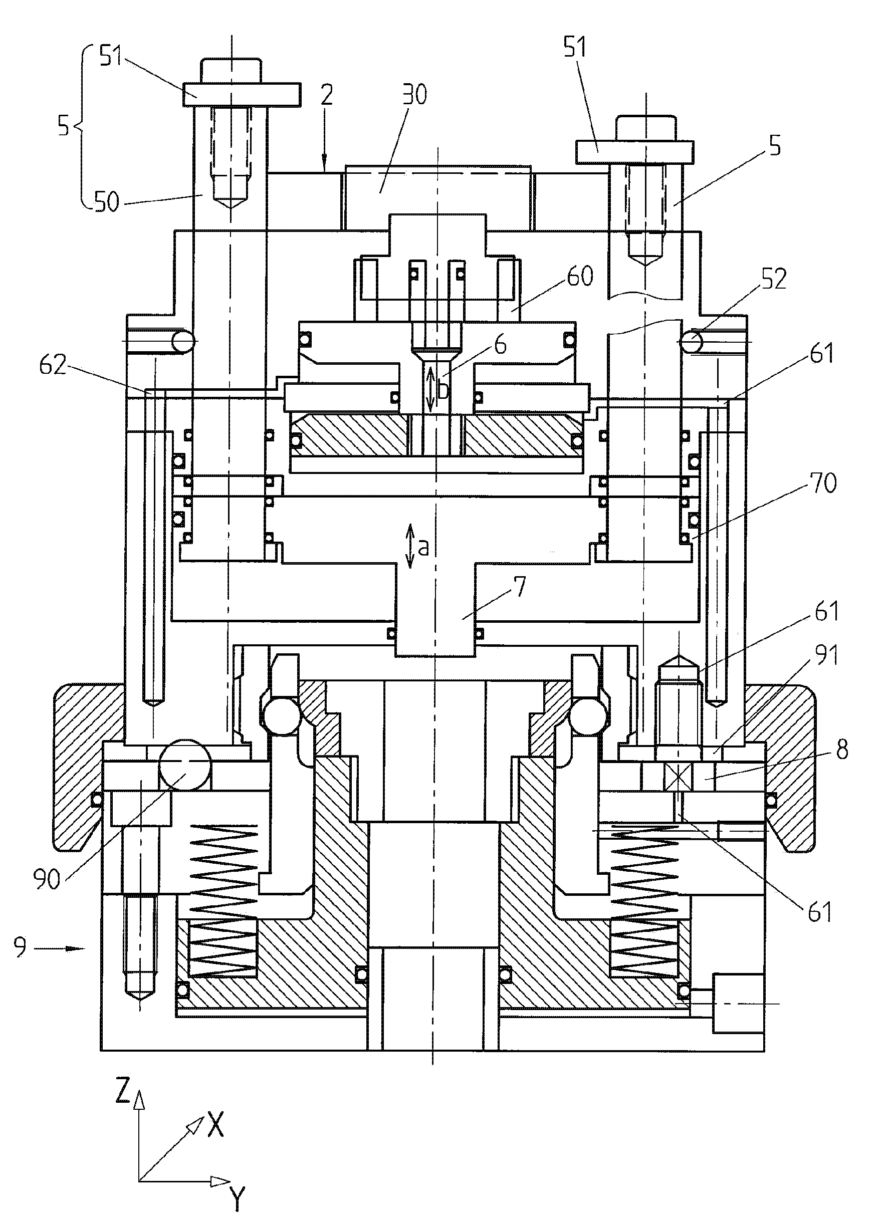
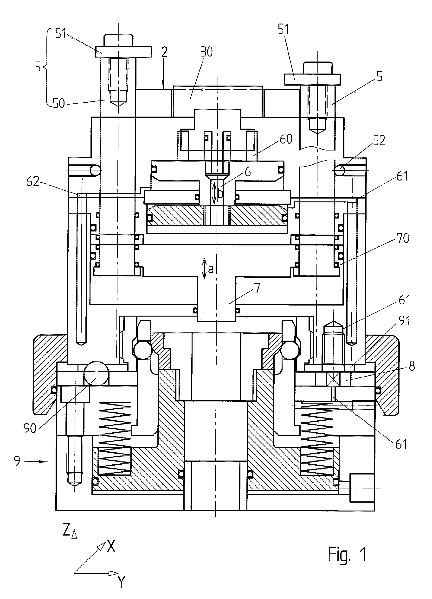
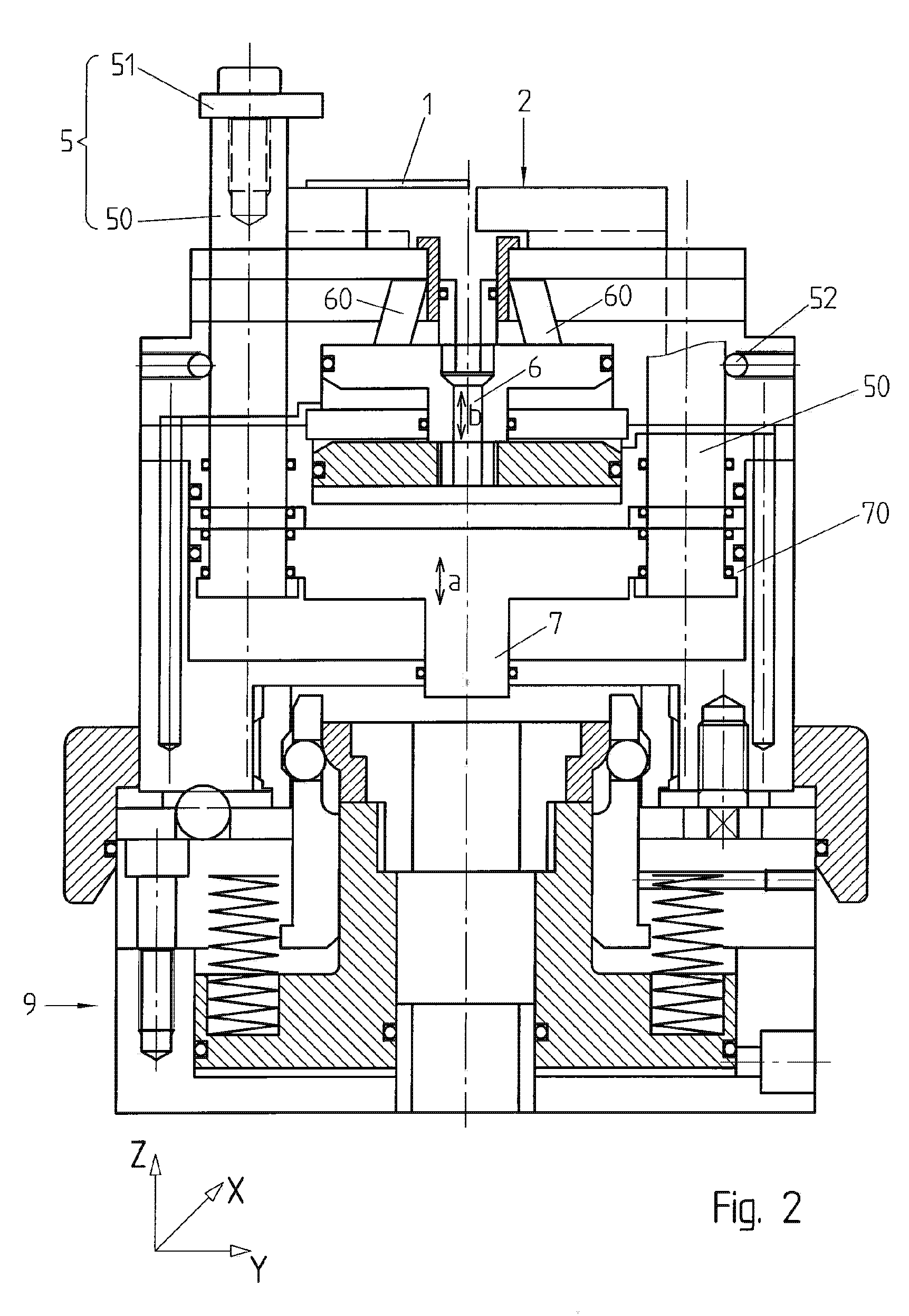
[0023]FIG. 4 illustrates an example of a part 1 capable of being held on a device according to the invention. The illustrated comprises an outer portion 10 and an inner portion 11. In the example illustrated, the inner portion is designed to be used as bridge or as bottom plate in a watch movement. The inner and outer portions are separated from one another by a pre-machined opening 14 and connected to one another by one or several links 12. The holding device of the invention allows for example the inner and outer portions of the part 1 to be held during cutting-off, i.e. during milling or cutting-off of the links 12 in order to separate the portions 10 and 11. Other operations can be performed on the held parts, including for example drilling, angling, engine turning, diamond finishing or other conceivable operations depending on the available tools.

[0024]The part 1 is relatively thin and comprises an upper surface 15 and a lower surface (not referenced). Traversing openings 13 al...


PUM

PropertyMeasurementUnit
Lengthaaaaaaaaaa
Displacementaaaaaaaaaa

Abstract

Part holding device for holding a part (1) while it is being machined, having:
    • a resting surface (2),
    • one or several mobile flanges (5) for pinning said part against the resting surface when the flanges rest against the upper side of said part, the flanges being capable of being raised when the part (1) is inserted and extracted,
    • one or several mobile jaws (3, 30) in a plane (X-Y) parallel to said resting surface in order to hold at least one portion (11) of said part by its lateral sides (16).

Description

REFERENCE DATA[0001]The present application claims priority of Swiss Patent Application CH06 / 1744, the content of which is hereby enclosed by reference.TECHNICAL FIELD[0002]The present invention concerns a part holding device for holding a part while it is being machined. The present invention concerns in particular a device allowing a fixed part to be held opposite a mobile tool, notably in a multi-axis machining center.[0003]Many solutions exist in the prior art for holding a part while it is being machined. Thick parts are often held by a vice or by a jaw resting on the outer lateral sides of the part. This solution is however not adapted for holding thin parts that would become deformed by a strong pressure on their lateral sides. In particular, the machining of bridges and bottom plates in watch-making require particular protection.[0004]There are also holding devices that make it possible to pin a part to be machined against a resting surface. One difficulty however arises whe...

Claims


Application Information

Patent Timeline
IPC IPC(8): B23Q3/08
CPCB23Q3/069Y10T409/303752G04D1/0078B25B5/003
Inventor YERLY, MICHEL
Owner YERLY MICHEL
Why Eureka
Try Eureka