Removeable attachment for a powered tool

a power tool and attachment technology, applied in the direction of manufacturing tools, metal sawing devices, portable power-driven tools, etc., can solve the problems of not being able to accomplish other tasks, sanding or cutting other materials, and using a hand-held saw dedicated to one task, such as a coping saw,

Inactive Publication Date: 2008-05-22
GLYNN JAMES P
View PDF23 Cites 22 Cited by
  • Summary
  • Abstract
  • Description
  • Claims
  • Application Information

AI Technical Summary

Problems solved by technology

However, using hand-held saws is a slow labor-intensive process.
In addition, a hand-held saw dedicated to one task, such as a coping saw, can not be used to accomplish other tasks, for example, sanding or cutting of other materials, including pipes, cables, beams, or other such tasks and / or materials.
Attempts have been made to develop powered hand-held saws, but none of these attempts have provided a powered hand-held saw that is both efficient and ergonomic while still providing precise control of the saw.
In addition, none of these attempts have provided an attachment that can be used with other power tools for multiple applications.

Method used


Image

  • Removeable attachment for a powered tool
  • Removeable attachment for a powered tool
  • Removeable attachment for a powered tool

Examples


Embodiment Construction

[0019]The following detailed description illustrates the invention by way of example and not by way of limitation. The description clearly enables one skilled in the art to make and use the invention, describes several embodiments, adaptations, variations, alternatives, and uses of the invention, including what is presently believed to be the best mode of carrying out the invention. Additionally, it is to be understood that the invention is not limited in its application to the details of construction and the arrangements of components set forth in the following description or illustrated in the drawings. The invention is capable of other embodiments and of being practiced or being carried out in various ways. Also, it is to be understood that the phraseology and terminology used herein is for the purpose of description and should not be regarded as limiting.

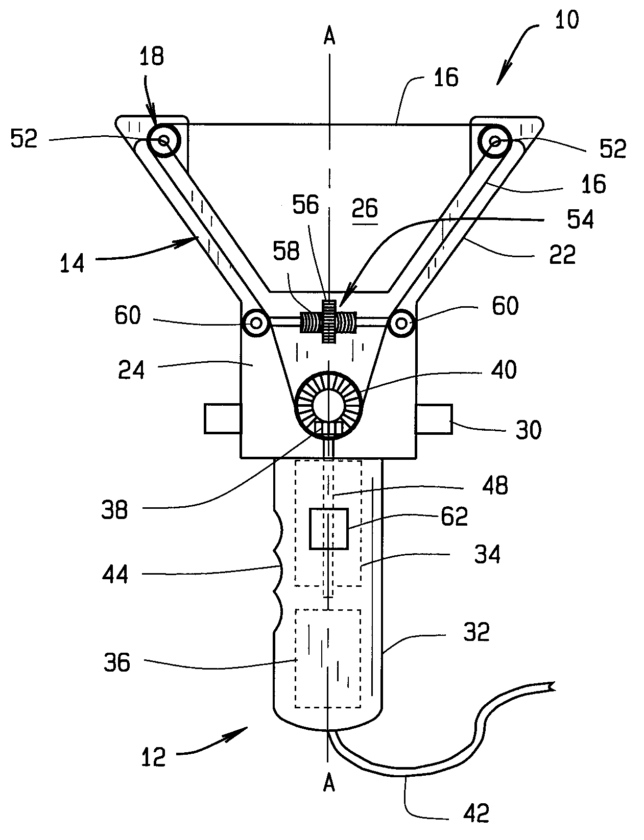
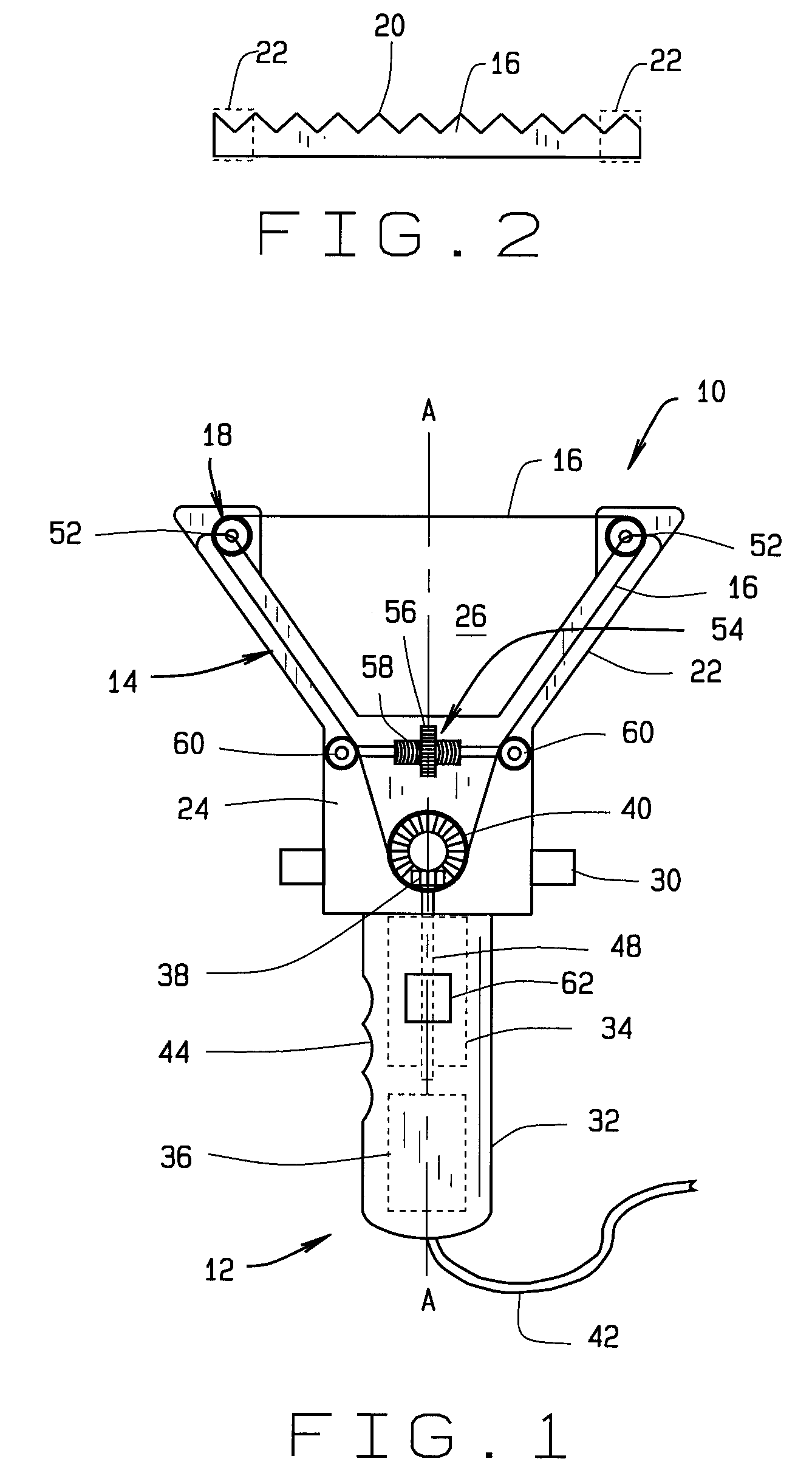
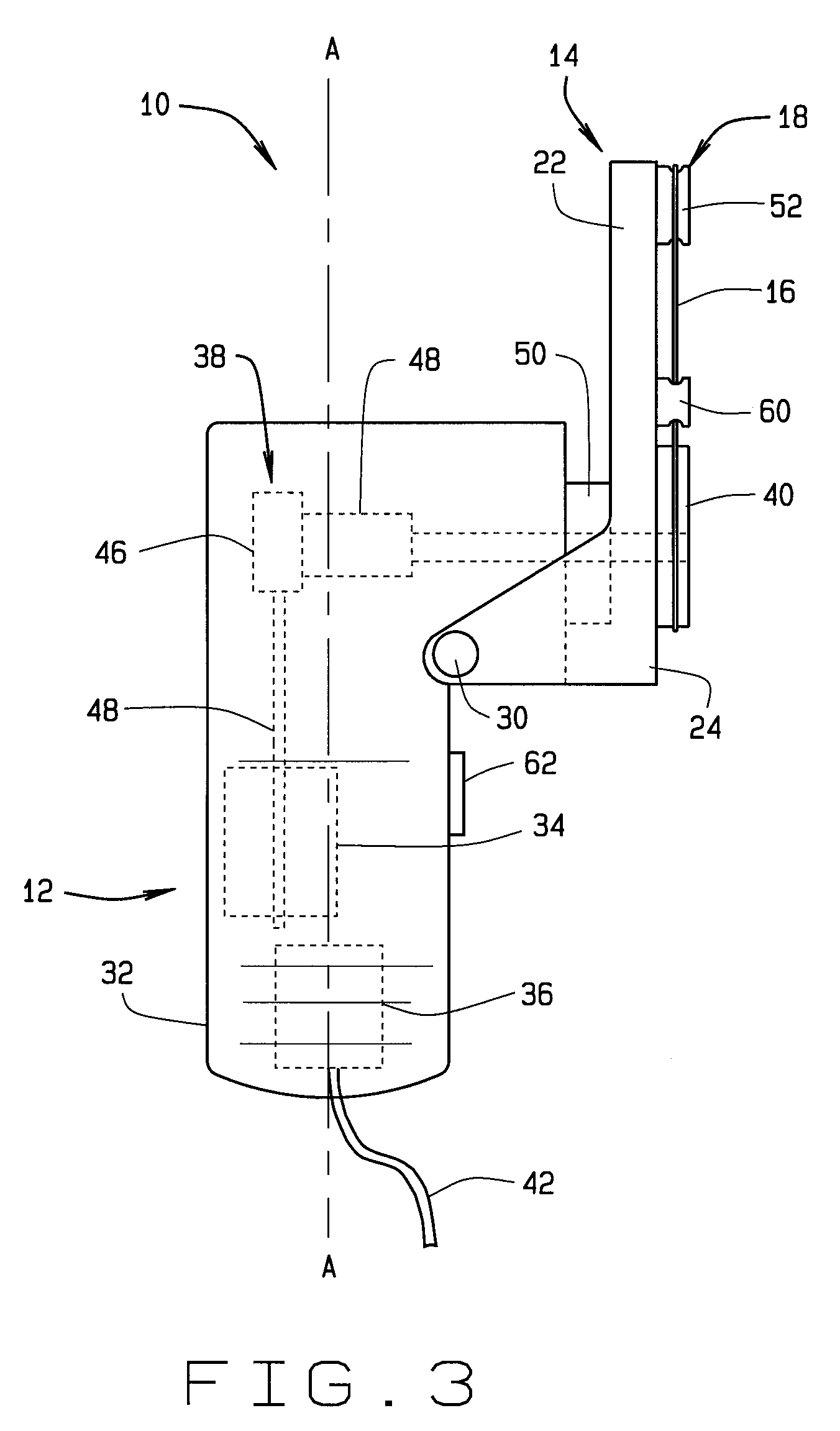
[0020]As shown in FIGS. 1-3, an embodiment of the present invention, generally referred to as a power tool attachment 10 for r...


PUM

PropertyMeasurementUnit
tensionaaaaaaaaaa
angleaaaaaaaaaa
lengthaaaaaaaaaa

Abstract

A removeable attachment for a powered tool includes a frame with a continuous loop blade positioned in a coplanar relationship with the frame along a system of blade guides so that a cutting surface of the blade faces a desired cutting area. The relative positions between the frame arms, the frame handle, and the blade provides a degree of stability and control that allows the operator to precisely and accurately control the cutting surface of the blade along curves, notches, and protrusions, including those involved in coping and sanding. In addition, this arrangement results in a compact design that positions the cutting surface in close proximity to the handle.

Description

CROSS-REFERENCE TO RELATED APPLICATIONS[0001]This application is related to U.S. Provisional Patent Application No. 60 / 859,392 filed Nov. 16, 2007 from which priority is claimed, and is hereby incorporated by reference, and is a continuation-in-part of U.S. patent application Ser. No. 10 / 585,683 filed Jul. 10, 2006 from which priority is claimed, and which is hereby incorporated by reference, which is a national phase application of International Application No. PCT / US2005 / 00146 filed Jan. 5, 2005, which priority is claimed, and which is hereby incorporated by reference, which claims priority to U.S. Provisional Patent Application No. 60 / 535,292 filed Jan. 9, 2004, and U.S. Provisional Patent Application No. 60 / 558,170 filed Mar. 31, 2004, the disclosures of which are hereby incorporated by reference.STATEMENT REGARDING FEDERALLY SPONSORED RESEARCH[0002]Not Applicable.BACKGROUND OF THE INVENTION[0003]This invention relates generally to hand-held cutting and sanding power tools.[0004...

Claims


Application Information

Patent Timeline
Patent Type & Authority Applications(United States)
IPC IPC(8): B23D51/10
CPCB23D57/0015B23D53/12
Inventor GLYNN, JAMES P.
Owner GLYNN JAMES P
Why Eureka
Try Eureka