Hunting stand

a technology for hunting stands and stands, applied in the field of hunting stands, can solve problems such as frustration in hunting

Inactive Publication Date: 2008-06-05
ARDISAM
View PDF41 Cites 47 Cited by
  • Summary
  • Abstract
  • Description
  • Claims
  • Application Information

AI Technical Summary

Benefits of technology

[0014]The present invention is also directed to a method of using a portable tree stand. A frame assembly is attached to a platform. The frame assembly includes at least one railing. At least one multi-directional seat is attached to the frame assembly at

Problems solved by technology

This limits the viewing direction as well as the shoo

Method used


Image

  • Hunting stand
  • Hunting stand
  • Hunting stand

Examples


Embodiment Construction

[0024]In the description which follows, like parts or elements are marked throughout the specification and drawings with the same reference numerals, respectively. The drawing figures are not necessarily to scale and certain features may be shown in somewhat generalized or schematic form in the interest of clarity and conciseness.

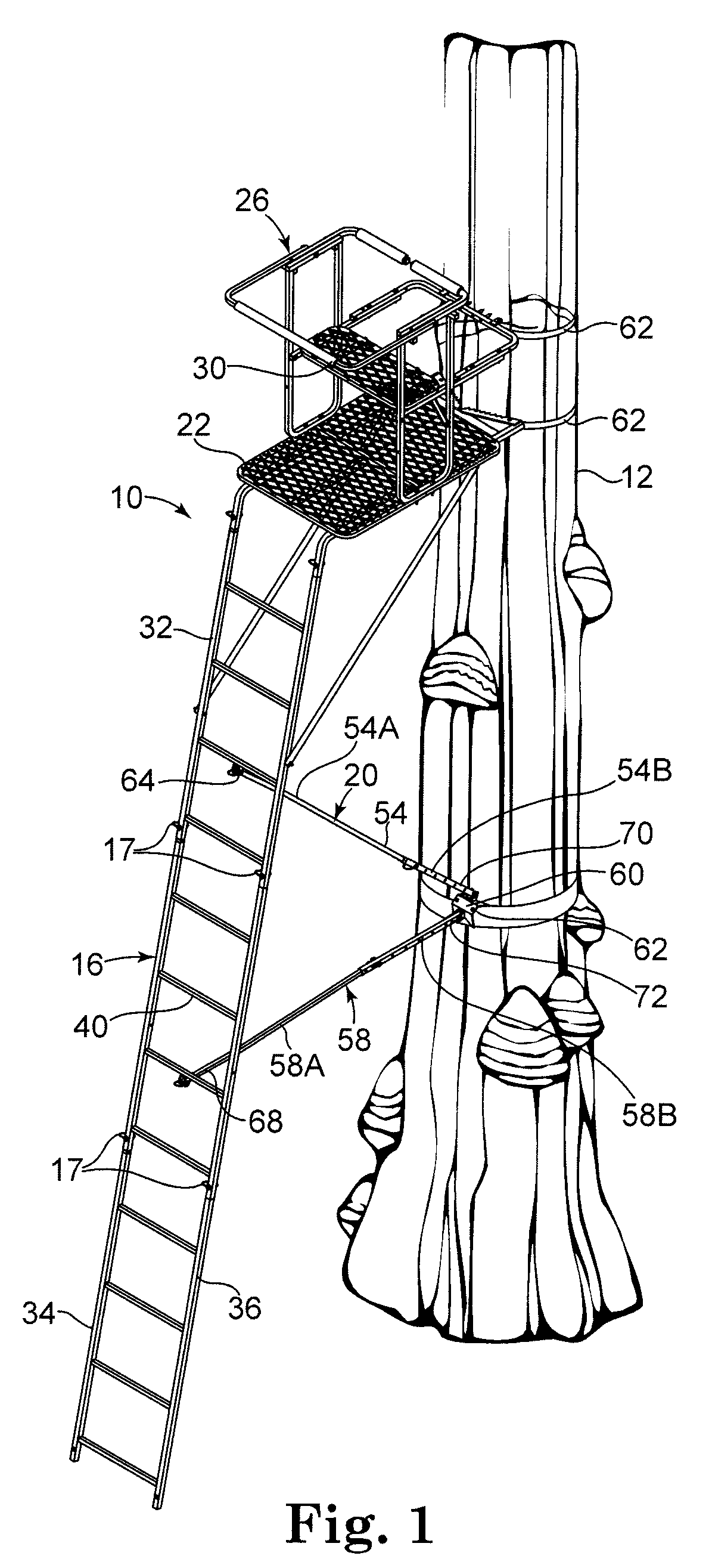
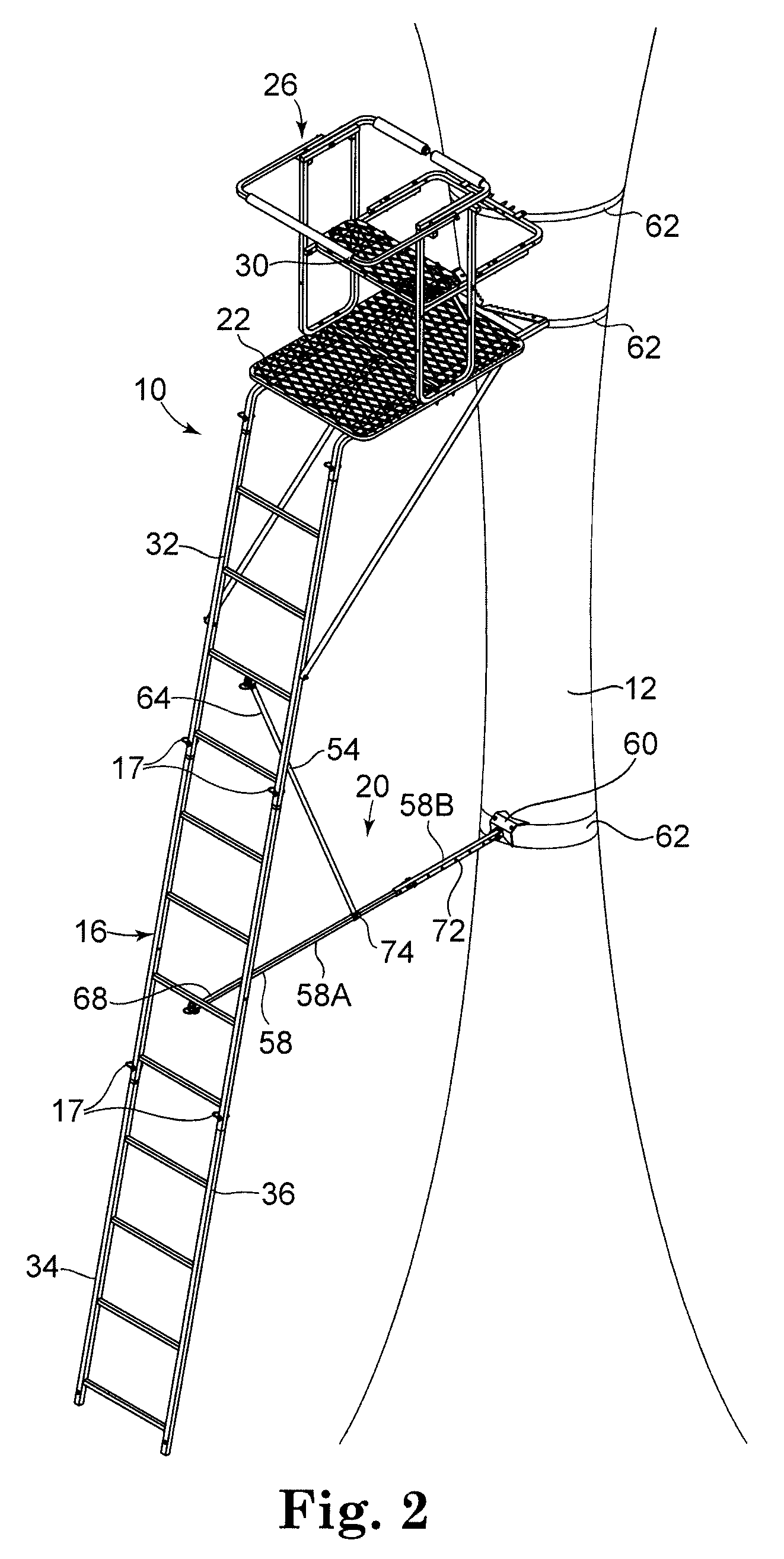
[0025]FIGS. 1-3 show perspective views of a portable tree stand 10 for use by game hunters and observers, in accordance with one embodiment of the present invention. As shown in FIG. 1, the tree stand 10 is secured to a tree 12 or another vertical support. The tree stand 10 includes a platform 22, a frame 26, and at least one multi-directional seat 30.

[0026]The portable tree stand 10 can be constructed of any suitable material capable of bearing weight and withstanding the weather elements. For example, the tree stand 10 may be constructed of powder-coated all-weather steel, fiber reinforced thermoset resins, natural or engineered wood products, composite m...


PUM


Abstract

A portable tree stand for elevating a hunter or observer above the ground is described. The tree stand can be sized such that it can accommodate one or two users. The tree stand includes a frame assembly that can be reconfigured to allow a user or users to face multiple directions. The railings are adjustable to maximize the functionality of the tree stand in each of the multiple directions.

Description

CROSS-REFERENCE TO RELATED APPLICATION[0001]This application claims priority from U.S. Provisional Patent Application No. 60 / 867,892, filed on Nov. 30, 2006, entitled “Hunting Stand,” which is incorporated herein by reference in its entirety.TECHNICAL FIELD[0002]The present invention relates generally to tree stands of the type adapted to be supported upon the trunk of a tree (or a similar vertical support) to elevate a hunter above the ground. More particularly, the present invention is directed to a portable tree stand which allows the hunter to face in multiple directions.BACKGROUND OF THE INVENTION[0003]Tree stands provide a number of practical advantages to the hunter. For example, the skilled hunter who must wait for relatively long periods of time until a suitable game animal approaches will find it desirable to assume a comfortable position where his view of the surrounding area is relatively unobstructed, and where his relative safety is assured. In areas of dense woods, it...

Claims


Application Information

Patent Timeline
IPC IPC(8): A01M31/02E06C7/16
CPCA01M31/02E06C7/182E06C7/16E06C1/34
Inventor ENGSTROM, JAY C.
Owner ARDISAM
Why Eureka
Try Eureka