
Stackable Storage Apparatus

a storage apparatus and rack technology, applied in the field of storage, can solve the problems of considerable cost of purchasing and assembling and the uncertainty of how much to spend on the vertical supports and horizontal shelves

Inactive Publication Date: 2008-06-12
BUSINESS SYST INT
View PDF15 Cites 17 Cited by
  • Summary
  • Abstract
  • Description
  • Claims
  • Application Information

AI Technical Summary

Benefits of technology

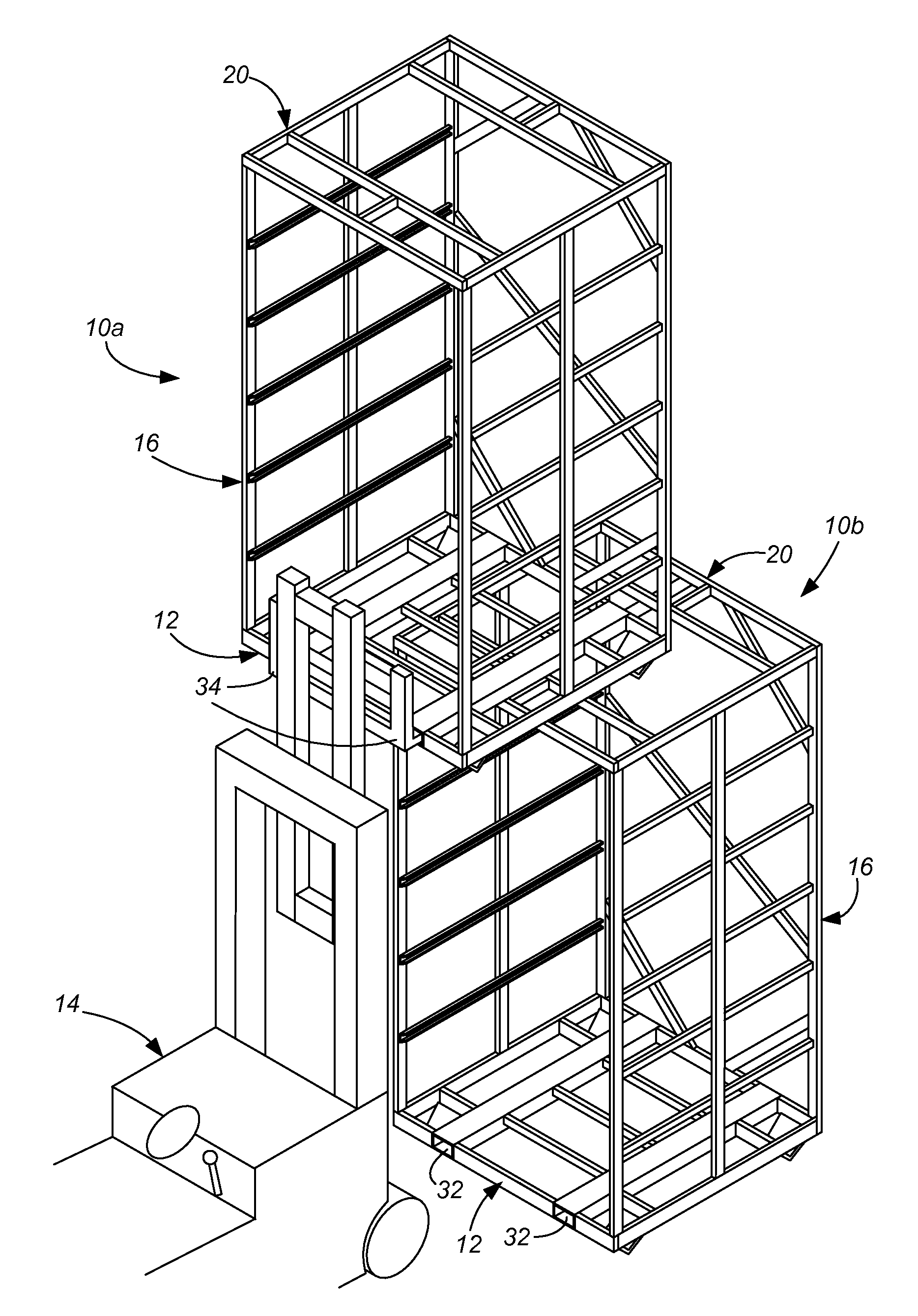
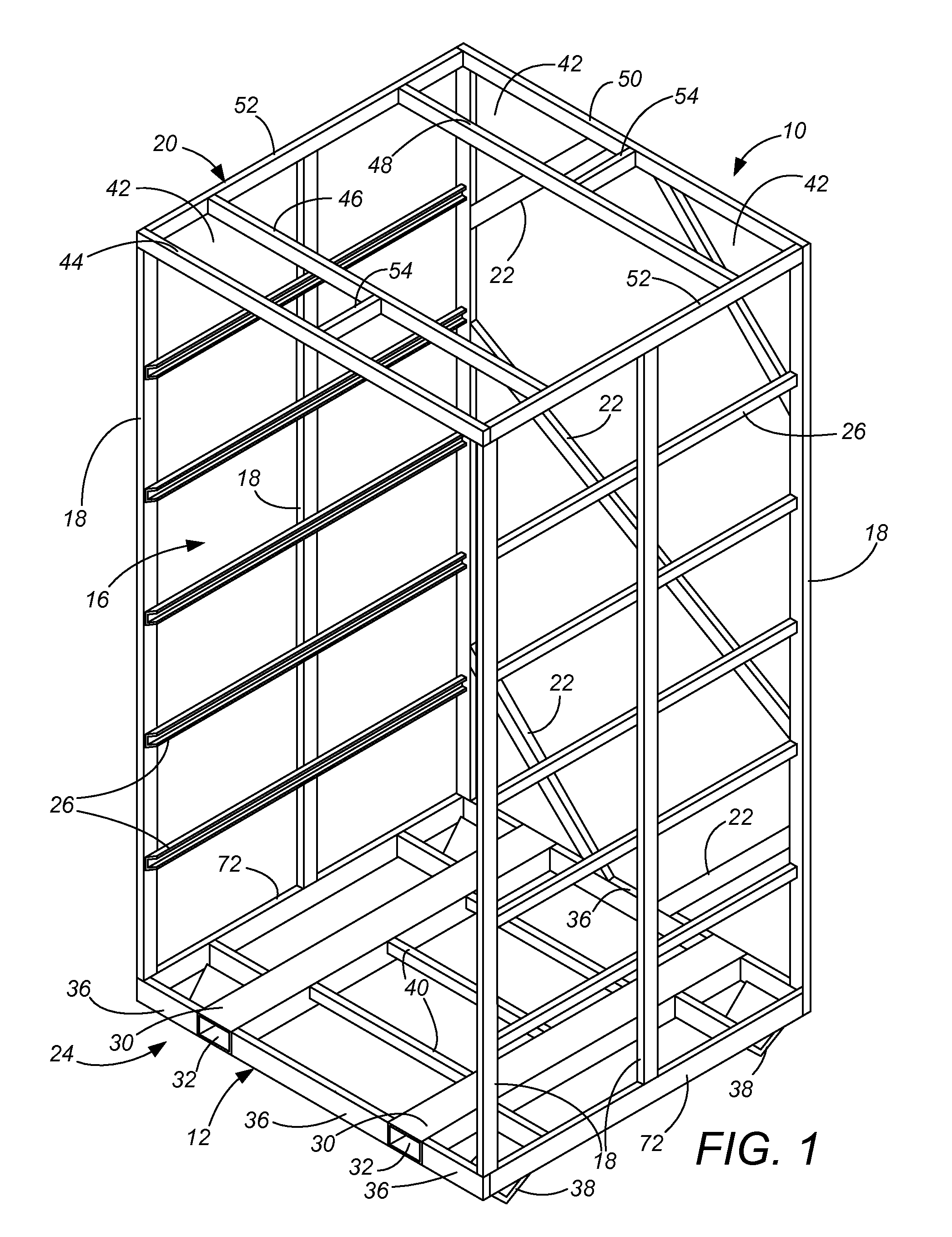
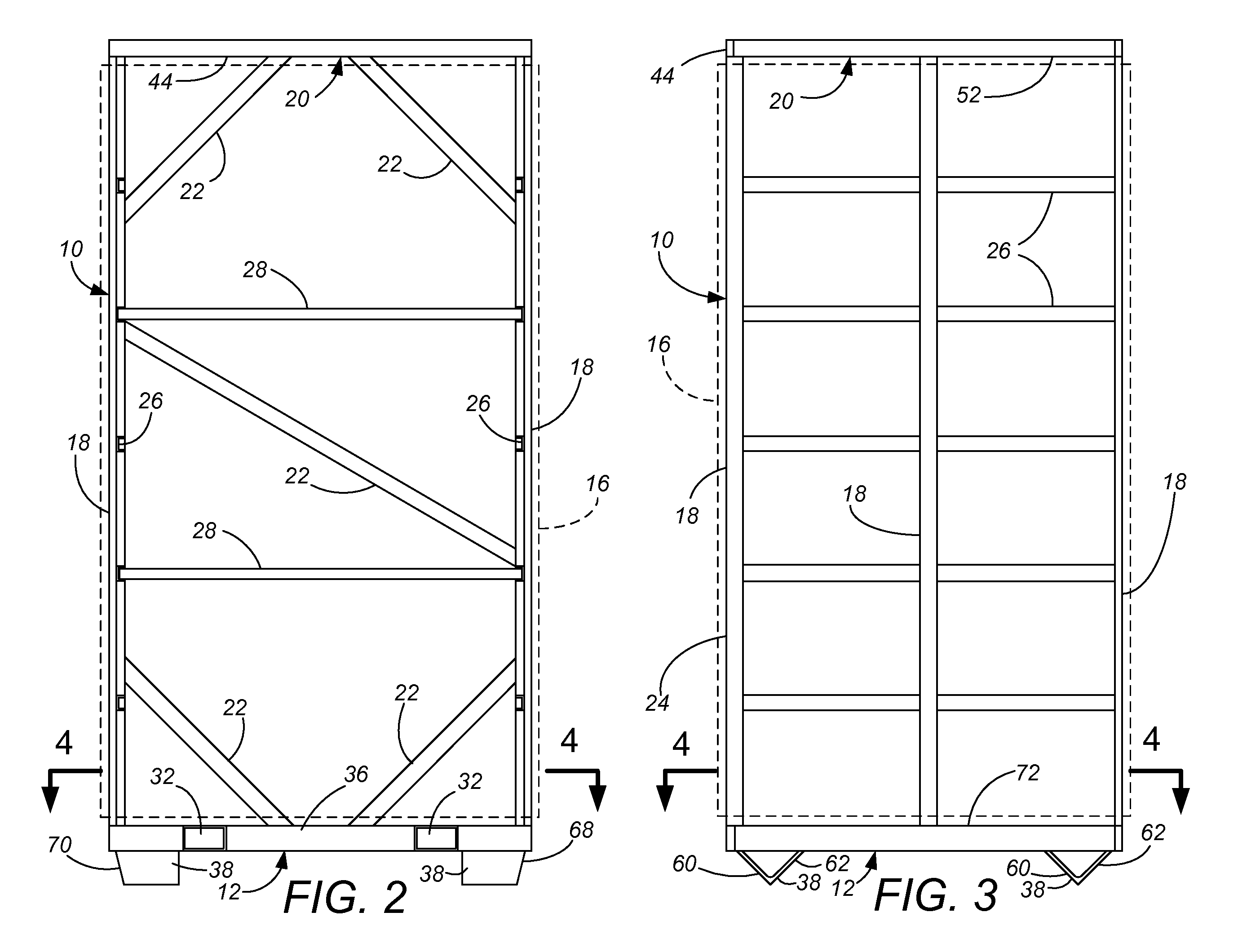
"The present invention is an apparatus that can be moved and stacked with other identical apparatuses using a tined lift such as a forklift. The apparatus has feet and support uprights that make it easy to stack. The front base cross member has targeting slopes to guide the second, upper shelf support apparatus down onto the first, lower shelf support apparatus. The top structure provides a top support perimeter that makes substantially perimetrical contact with the base of the apparatus stacked thereon. The technical effects of this invention are improved stability and stackability of the shelf unit, making it easier to move and use in various situations."

Problems solved by technology

The cost of purchasing and assembling the vertical supports and horizontal shelves is considerable.
In many instances, it is not known how many items need be stored in the warehouse, and the uncertainty in how much storage space is needed in turn leads to uncertainty in how much to spend on the vertical supports and horizontal shelves while constructing and laying out the warehouse.

Method used


Image

  • Stackable Storage Apparatus
  • Stackable Storage Apparatus
  • Stackable Storage Apparatus

Examples


Embodiment Construction

[0015]The present invention generally relates to an apparatus that is stackable. Each of the apparatus has base with targeting slopes and structures that are adapted to receive the tines of a forklift. The apparatus also includes a structure that forms the top of the apparatus, and this top structure mates with the base of an overlying structure during stacking, includes structures for receiving the targeting slopes When stacking two or more of the apparatuses, targeting slopes facilitate guiding the base of the upper apparatus onto the top structure of the lower apparatus. Furthermore, to provide support, when two apparatuses are stacked, the base of the overlying apparatus is in contact with the top structure of the underlying apparatus. Furthermore, in one embodiment, the base is configured with feet of a height that would enable a pallet jack to be placed under the base.

[0016]A first embodiment of a shelf storage apparatus 10 in accordance with one embodiment of the present inve...


PUM


Abstract

Shelf support apparatus can be moved and stacked with a tined lift such as a forklift. The apparatus has based feet disposed lower than a front base cross member, and support uprights extend upward therefrom to a generally horizontal top structure. The front base cross member has two tine openings with lift tubes for receiving lift tines of a fork lift, and a bottom surface for receiving lift tines of a floor pallet jack. The top structure includes feet-receiving openings corresponding in location to the base feet, such that the apparatus can be stacked. The base feet have targeting slopes both in a front-to-back direction and in a side-to-side direction, to guide the second, upper shelf support apparatus down onto the first, lower shelf support apparatus with the base feet received in a nesting relationship. The targeting slopes in the front-to-back direction acts over a targeting area which is greater than the targeting area in the side-to-side direction. The top structure also provides a top support perimeter which makes substantially perimetrical contact with the base of the apparatus stacked thereon.

Description

CROSS-REFERENCE TO RELATED APPLICATION(S)[0001]This application claims priority from provisional application No. 60 / 814,413, filed Jun. 19, 2006.BACKGROUND OF THE INVENTION[0002]The present invention relates to the field of warehousing, and particularly to the design and manufacture of apparatus, for storing material, which can be stacked one on top of another and moved with a tined lift such as a forklift or pallet lift. It is common in a wide array of industries to store items in warehouses. In general, the warehouse is a large, roofed structure having a horizontal floor upon which a tined lift such as a forklift or pallet lift is driven. In the most common warehouse layout, vertical supports are attached to the floor or assembled in a grid layout spanning a significant area of the warehouse, with a number of horizontal shelves arranged between the vertical supports. Pallets are then used underneath the items being stored. The pallets provide tine openings for the tines of the lif...

Claims


Application Information

Patent Timeline
Patent Type & Authority Applications(United States)
IPC IPC(8): A47F5/00
CPCB65D19/10B65D2519/00024B65D2519/00059B65D2519/00164B65D2519/00199B65D2519/00298B65D2519/00965B65D2519/00512B65D2519/00562B65D2519/00621B65D2519/00666B65D2519/00716B65D2519/0096B65D2519/00338
Inventor PETERS, ROGERKELSEY, MAXWELLWHEELER, DAVID
Owner BUSINESS SYST INT
Learn More