Threaded union nut and sliding hammer for rotating same

a technology of sliding hammer and union nut, which is applied in the direction of threaded fasteners, hose connections, screws, etc., can solve the problems of difficult and/or dangerous, difficult to repeatedly strike the desired lug b>14/b> squarely and solidly, and more difficult to avoid glancing blows

Inactive Publication Date: 2008-06-12
FMC TECH INC
View PDF37 Cites 14 Cited by
  • Summary
  • Abstract
  • Description
  • Claims
  • Application Information

AI Technical Summary

Problems solved by technology

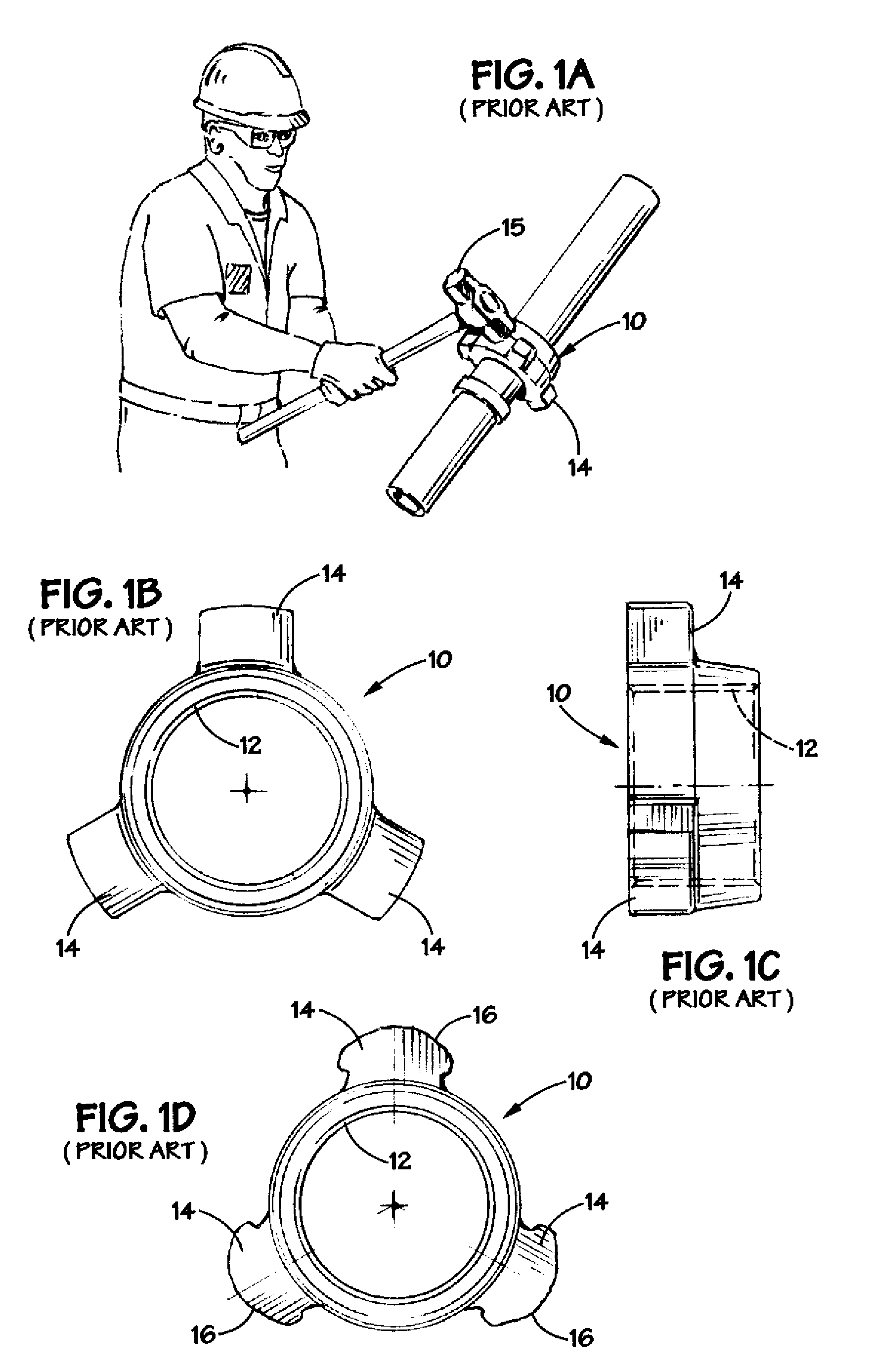
Additionally, such wing union nuts 10 may be located at places that are difficult and / or dangerous to access, e.g., at elevated locations on an offshore drilling rig.
There are several problems associated with the tightening and loosening of such prior art wing union nuts 10.
Even in conditions where such a prior art wing union nut 10 is readily accessible, it is difficult to repeatedly strike the desired lug 14 squarely and solidly.
Such sloped or rounded sidewalls make it even more difficult to avoid a glancing blow when striking such damaged lugs 14 with a hammer.
Such actions may be problematic in that the hammer 15 may strike other equipment, other personnel and / or injure the person swinging the hammer 15.

Method used


Image

  • Threaded union nut and sliding hammer for rotating same
  • Threaded union nut and sliding hammer for rotating same
  • Threaded union nut and sliding hammer for rotating same

Examples


Embodiment Construction

[0024]Illustrative embodiments of the invention are described below. In the interest of clarity, not all features of an actual implementation are described in this specification. It will of course be appreciated that in the development of any such actual embodiment, numerous implementation-specific decisions must be made to achieve the developers' specific goals, such as compliance with system-related and business-related constraints, which will vary from one implementation to another. Moreover, it will be appreciated that such a development effort might be complex and time-consuming, but would nevertheless be a routine undertaking for those of ordinary skill in the art having the benefit of this disclosure.

[0025]The present invention will now be described with reference to the attached figures. The words and phrases used herein should be understood and interpreted to have a meaning consistent with the understanding of those words and phrases by those skilled in the relevant art. No...


PUM


Abstract

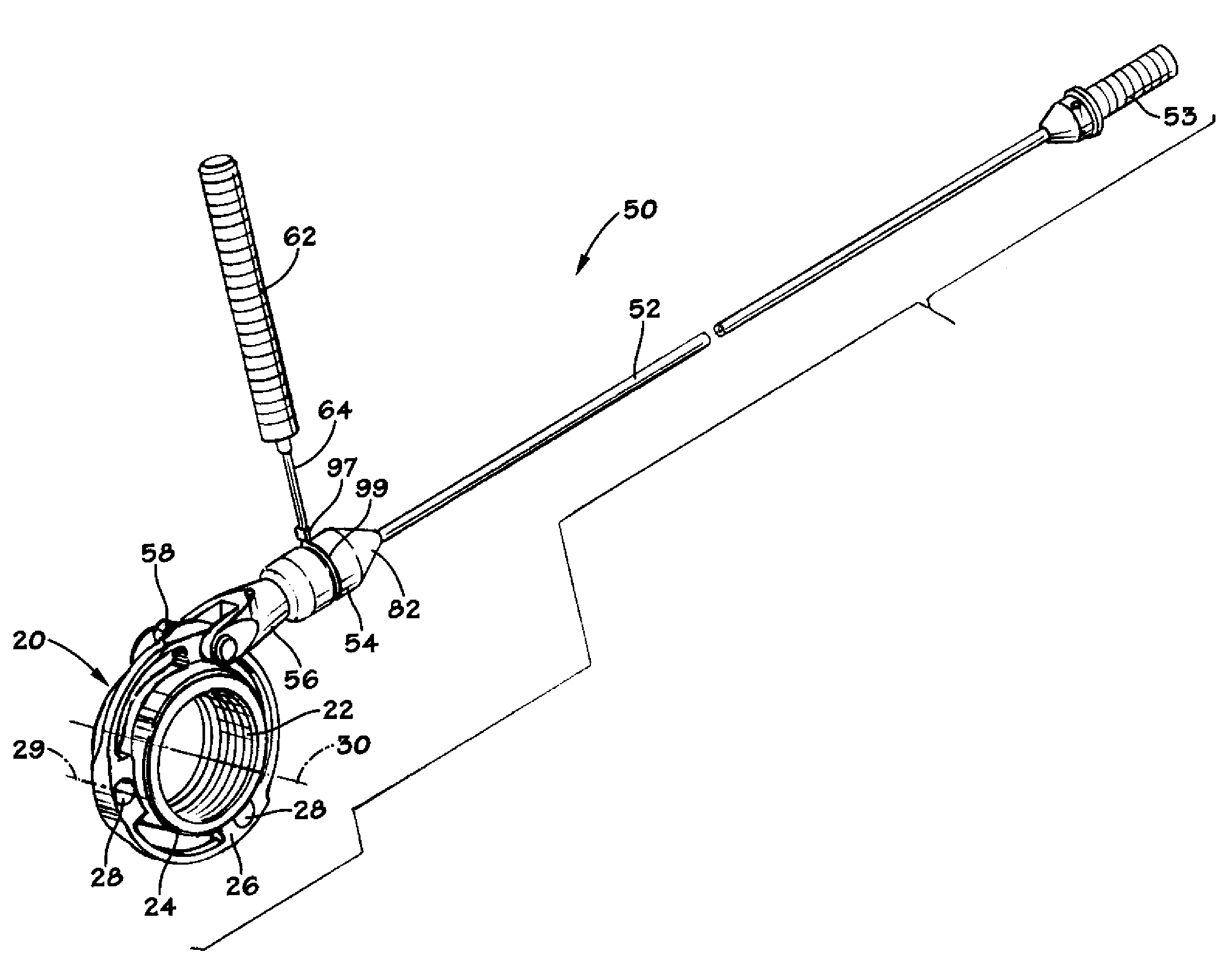
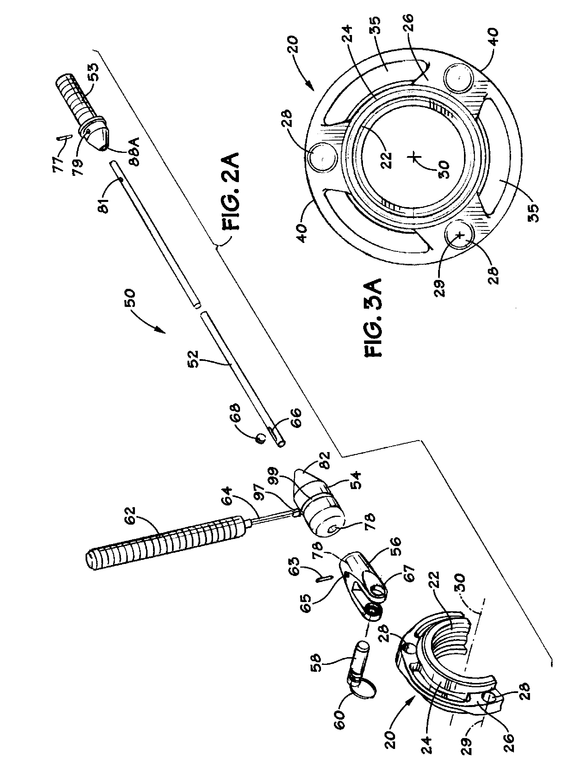
A threaded union nut is disclosed which includes a body, a threaded opening formed in the body and a web including a plurality of impact openings that are radially offset from a centerline of the threaded opening, wherein the impact openings are adapted to be engaged by a device so as to rotate the threaded union nut. A sliding hammer is also disclosed which includes a guide rod, a structural member coupled to the guide rod and a hammer having an internal bore adapted to receive the guide rod therein. The sliding hammer further includes a flexible cable and a swing handle, wherein the cable is coupled to the hammer and to the swing handle. The hammer is adapted to strike the structural member.

Description

BACKGROUND OF THE INVENTION[0001]1. Field of the Invention[0002]The present invention is generally related to the field of threaded connectors, and, more particularly, to a union nut and a sliding hammer for rotating the union nut.[0003]2. Description of the Related Art[0004]There are a number of applications in many industries, such as the oil and gas industry, which require the coupling of components to one another by threaded connectors. For example, threaded nuts, caps or other devices may be used to close the end of a pipe, close the outlet of a piece of equipment, or to connect threaded components to one another. FIGS. 1A-1D depict an illustrative wing union nut 10 that is in widespread use in the oil and gas industry. The wing union nut 10 comprises a threaded opening 12 and a plurality of radially extending lugs 14.[0005]Typically, such wing union nuts 10 are tightened or loosened by a person striking one of the lugs 14 with a hammer 15. The effectiveness of such hammer stri...

Claims


Application Information

Patent Timeline
Patent Type & Authority Applications(United States)
IPC IPC(8): F16L55/00
CPCF16B23/0069B25B19/00
Inventor UNGCHUSRI, TEPGARNER, WILLIAM H.SOLTAU, JAMES R.KILLINGSWORTH, ALAN R.
Owner FMC TECH INC
Why Eureka
Try Eureka