Surgical Device for The Collection of Soft Tissue

a surgical device and soft tissue technology, applied in the field of tissue sampling devices, can solve the problems of many time-consuming steps in getting the biopsy device properly positioned, no single procedure is ideal for all cases, and the degree of freedom of movement of the mounting arm may be hindered in certain parts of the breas

Inactive Publication Date: 2008-06-19
DEVICOR MEDICAL PROD
View PDF98 Cites 109 Cited by
  • Summary
  • Abstract
  • Description
  • Claims
  • Application Information

AI Technical Summary

Benefits of technology

[0024]The present invention further includes a cutter axial transmission contained within the handpiece and operationally connected to the elongated cutter. When the cutter axial transmission is actuated, the cutter is slid in an axial direction relative to the piercer. It is slid in the distal axial direction to cut a portion of tissue protruding into the port. It is slid in the proximal axial direction to retrieve the cut portion of tissue from the biopsy instrument.

Problems solved by technology

The type of biopsy used depends mainly on various factors present in the patient, and no single procedure is ideal for all cases.
As this brief description illustrates, there are many time consuming steps in getting the biopsy device properly positioned to retrieve the desired tissue.
In addition, the accessibility of certain parts of the breast may be hindered by the degrees of freedom of the movement of the mounting arm.
Also, the size of the stereotactic table and associated equipment precludes portability of the system.
It is not possible, for example, to have a number of patients being prepared for the procedure in separate rooms of a clinic, if there is only one room set-up for doing the procedure.
Many of these devices are for arthroscopic surgery and are not intended for retrieving biopsy core samples of tissue for pathological analysis.
However, the device does not incorporate a vacuum source for obtaining the tissue portion.
Capturing more tissue with each sample reduces the number of samples required, and increases the likelihood of obtaining the diseased tissue.
The Terwilliger device in '061 also does not address how to minimize leakage and spilling of the high volume of fluids present in biopsy procedures.

Method used


Image

  • Surgical Device for The Collection of Soft Tissue
  • Surgical Device for The Collection of Soft Tissue
  • Surgical Device for The Collection of Soft Tissue

Examples


first embodiment

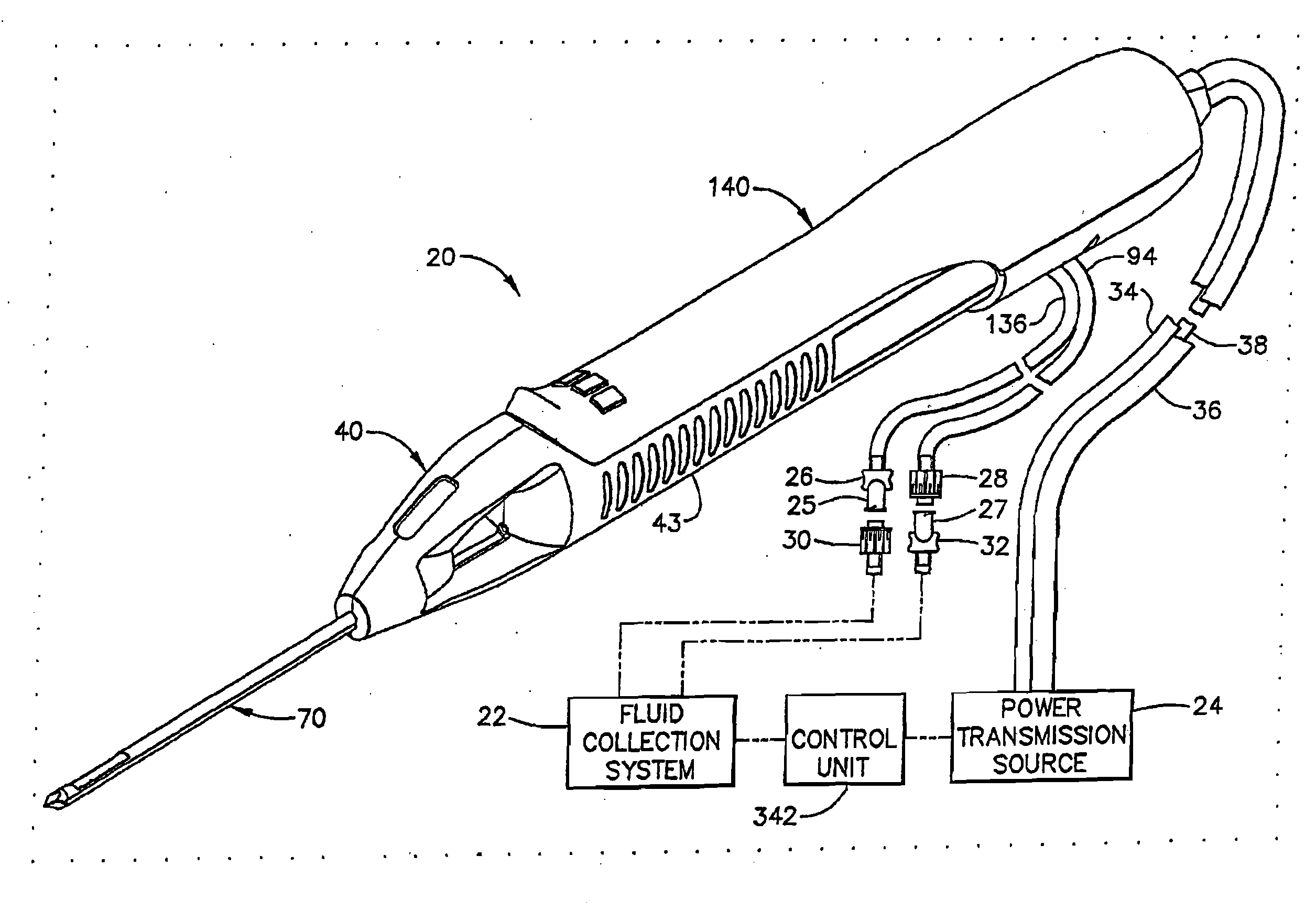
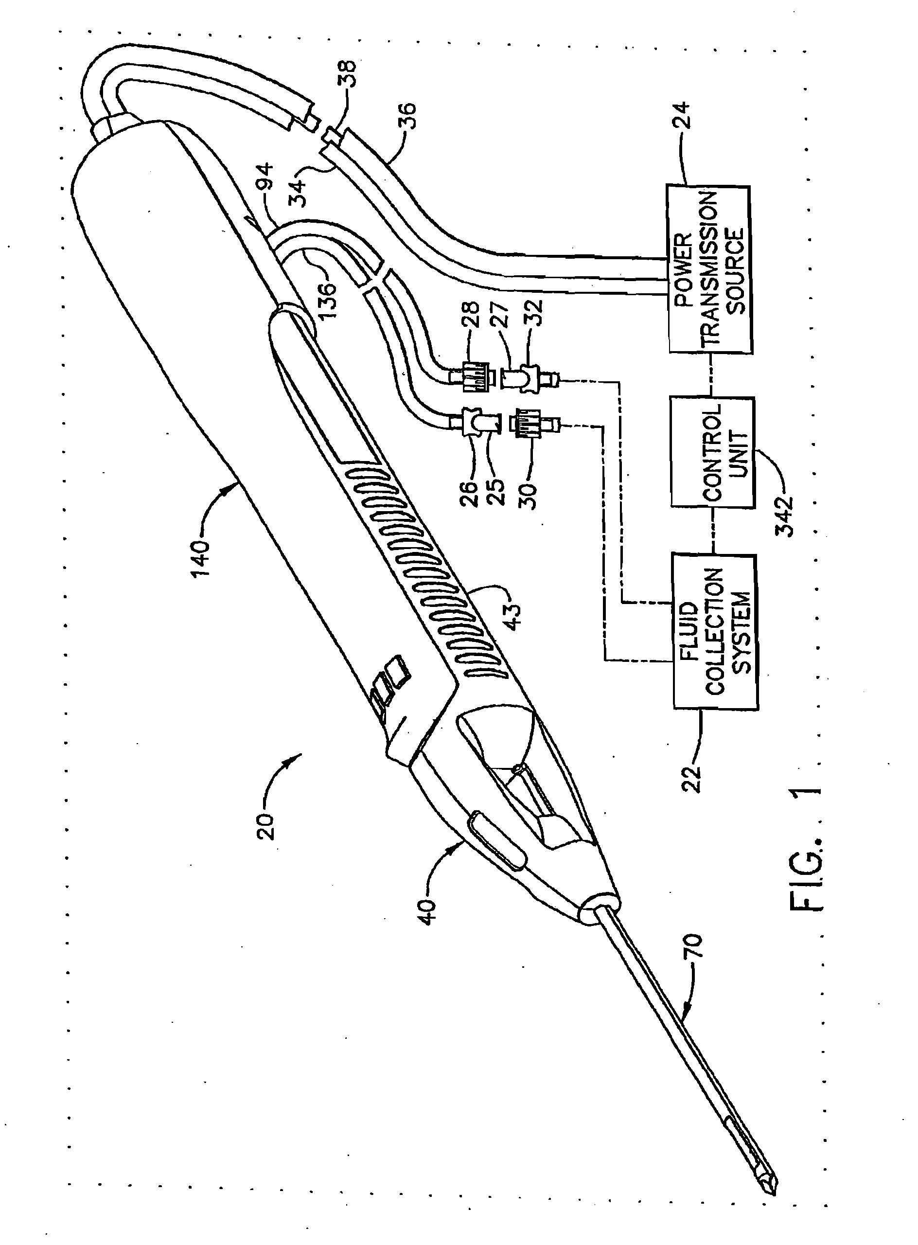
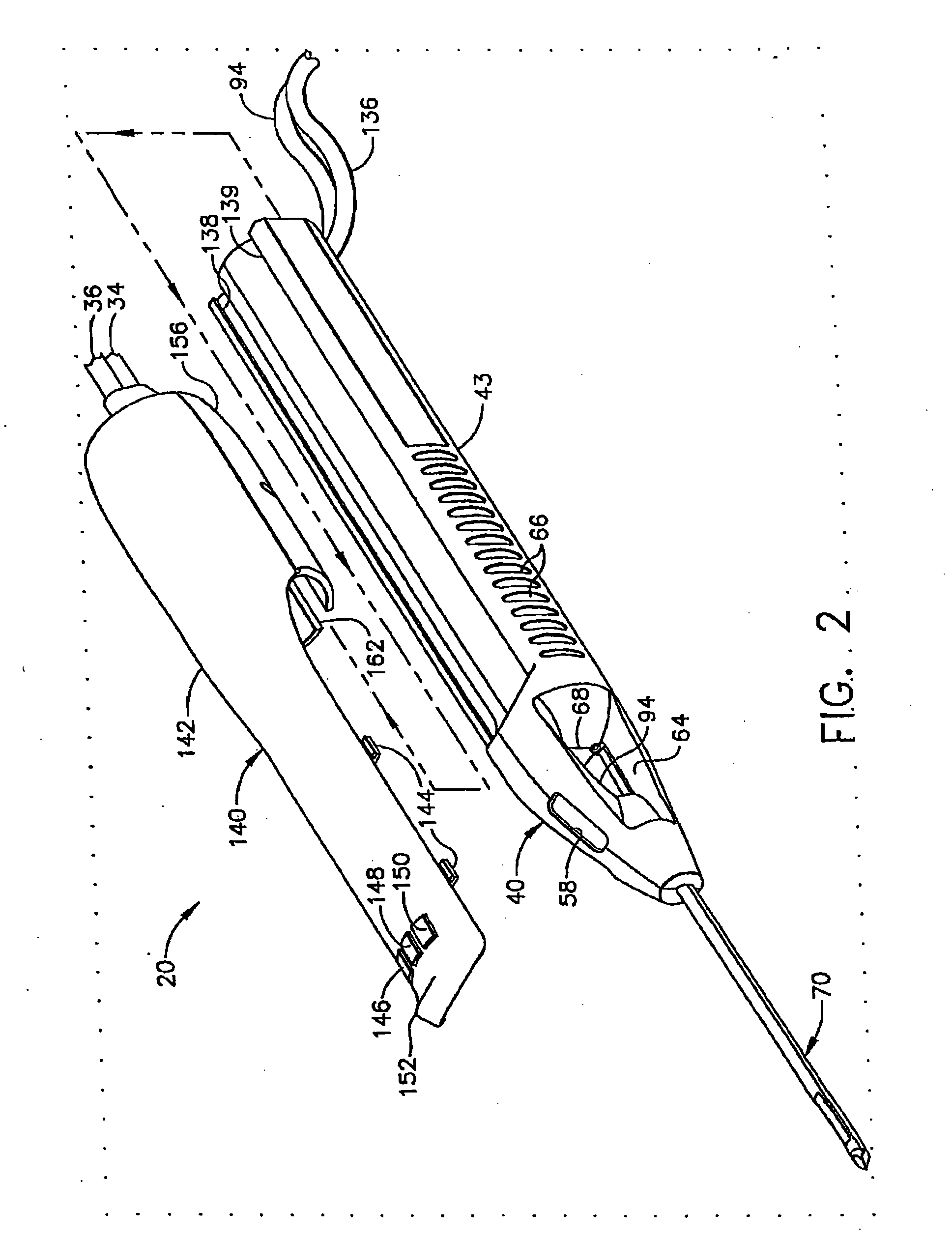
[0047]FIG. 1 shows a biopsy instrument comprising a probe assembly 40, a holster 140, a fluid collection system 22, a control unit 342, and a power transmission source 24. The probe assembly 40 is detachably connected to the holster 140. Together they constitute a lightweight, ergonomically shaped, hand manipulatable portion referred to as a handpiece 20. The probe assembly 40 includes a piercer 70 extending distally from a hollow handle 43. The probe assembly 40 is fluidly connected to the fluid collection system 22 by a first vacuum tube 94 and a second vacuum tube 136. The first and second vacuum tubes are detachably connected to the fluid collection system 22 by a first connector 27 and a second connector 25, respectively. The first connector has a male portion 32 and a female portion 28 attached to the first vacuum tube 94. The second connector 25 has a female portion 30 and a male portion 26 attached to the second vacuum tube 136. The connector portions, 26, 28, 30, and 32, ar...

second embodiment

[0073]FIG. 11 shows an isometric view of the probe lower shell 208 and the holster lower shell 222 of the biopsy instrument 201 of the present invention. The view is shown with the bottom side up in order to clearly present a probe latch 220 which is molded as a cantilever into the probe lower shell 208, and can be deflected downwards by a force applied to a latch ramp surface 223. The latch 220 further comprises a latch projection 219 for insertion into a holster slot 224 as the probe assembly is inserted into the holster 221. The ramp surface 220 is deflected downwards by interaction with an inside surface 225 of the holster shell 222 and retainably snaps into a slot key 226 when the probe assembly is fully inserted into the holster, thus rotationally engaging the left and right couplers, 240 and 238, to the drive shaft 212 and the gear shaft 210, respectively, as shown in FIG. 10. To remove the probe assembly from the holster, one must press on the projection 219 while pulling th...

third embodiment

[0076]FIG. 14 shows the relationship of the electro-mechanical components of the present invention to the control unit 342. the present invention is depicted and includes the holster 251 of FIG. 13. A first motor / tachometer combination 338 (sometimes referred to as a first motor / tach) and a second motor / tachometer combination 340 (sometimes referred to as a second motor / tach) are depicted as part of the power transmission source 24, and transmit rotational power to the holster 251 via the first and second rotatable shafts, 264 and 266, respectively. The motor / tach combinations, 340 and 348, are comniercially available as DC MicroMotors Series 3863, MicroMo Electronics, Inc. The control cord 265 is electrically connected to a serial controller 380 available as Part No. MCF5206eFT40 from Motorola, Inc. A serial controller 380 is electronically connected to the switchboard 274 by ribbon cable 270 and control cord 265. The serial controller 380 coordinates information exchange across th...


PUM


Abstract

A handheld biopsy device is provided for the collection of soft tissue samples from a surgical patient. In a preferred embodiment, the biopsy device comprises a handpiece, a fluid collection system, and a power transmission source. The handpiece is configured for grasping by a single hand, and being independently manipulatable by hand for movement of the instrument toward and away from the patient. An elongated piercer extends from the distal end of the handpiece. The piercer has a sharpened distal end for entering the tissue and a port located proximal to the sharpened distal end for receiving a portion of tissue mass. An elongated cutter is disposed coaxially relative to a piercer lumen of the piercer. A distal blade of the cutter slides distally past the port of the piercer to severe the tissue portion drawn into the port by vacuum. The cutter is retracted to a most proximal position for removal of the tissue portion from a cutter lumen of the cutter. The handpiece further comprises a holster for detachably connecting a cutter rotation transmission and a cutter axial transmission to the power transmission source.

Description

RELATED PATENTS AND PATENT APPLICATIONS[0001]This application claims priority to U.S. patent application Ser. No. 10 / 638,519 Filed Aug. 11, 2003, which claims priority to U.S. Ser. No. 09 / 895,732 filed Jun. 29, 2001; which claims priority to Ser. No. 09 / 543,122 filed Apr. 5, 2000; which claims priority Ser. No. 09 / 178,075 filed Oct. 23, 1998.[0002]This application is related to the following co-pending U.S. patent applications: Ser. No. 08 / 825,899 filed on Apr. 2, 1997; Ser. No. 09 / 107,845 filed on Jun. 30, 1998. This application is farther related to the following co-pending U.S. patent application Ser. No. ______, filed (Attorney Docket No. END 562); Ser. No. ______, filed (Attorney Docket No. END 563).FIELD OF THE INVENTION[0003]The present invention relates, in general, to devices for tissue sampling and, more particularly, to improved biopsy probes for acquiring subcutaneous biopsies and for removing lesions.BACKGROUND OF THE INVENTION[0004]The diagnosis and treatment of patien...

Claims


Application Information

Patent Timeline
Patent Type & Authority Applications(United States)
IPC IPC(8): A61B10/02
CPCA61B10/0275A61B10/0266A61B2017/00367A61B10/0283A61B34/25A61B90/37A61B2010/0208
Inventor PRIVITERA, SALVATOREHIBNER, JOHN A.BUZZARD, JON D.PILLER, MICHAEL E.IVERSON, DAVID S.REITER, MICHAEL J.
Owner DEVICOR MEDICAL PROD
Why Eureka
Try Eureka