
Eureka
For R&D, Eureka makes reading and utilizing patents & technical documents easy.
Eureka AIR
Designed for self-driven R&D workflows. Generate viable solutions, solve complex R&D challenges, empower your innovation with AI.

Eureka Materials
Designed for material experts only. Revolutionize your material R&D, from search, analyze, to developing new materials.

TechResearch
Generate reliable direction feasibility study reports for your R&D in just a few steps.

TechSeek
Discover and master advanced knowledge NOW. Basics, ideas, possibilities, all at once.

TechMind
As an expert in R&D Theories, TechMind can generates customized viable solutions instantly.

TechRisk
Analyze your overall solution with one click, know your potential R&D risks in advance.

TechMonitor
Get weekly tech updates, stay abreast of the latest tech innovations and key insights.
Power transmission device of a compressor
- Summary
- Abstract
- Description
- Claims
- Application Information
AI Technical Summary
Problems solved by technology
Method used
Image

Examples
first embodiment
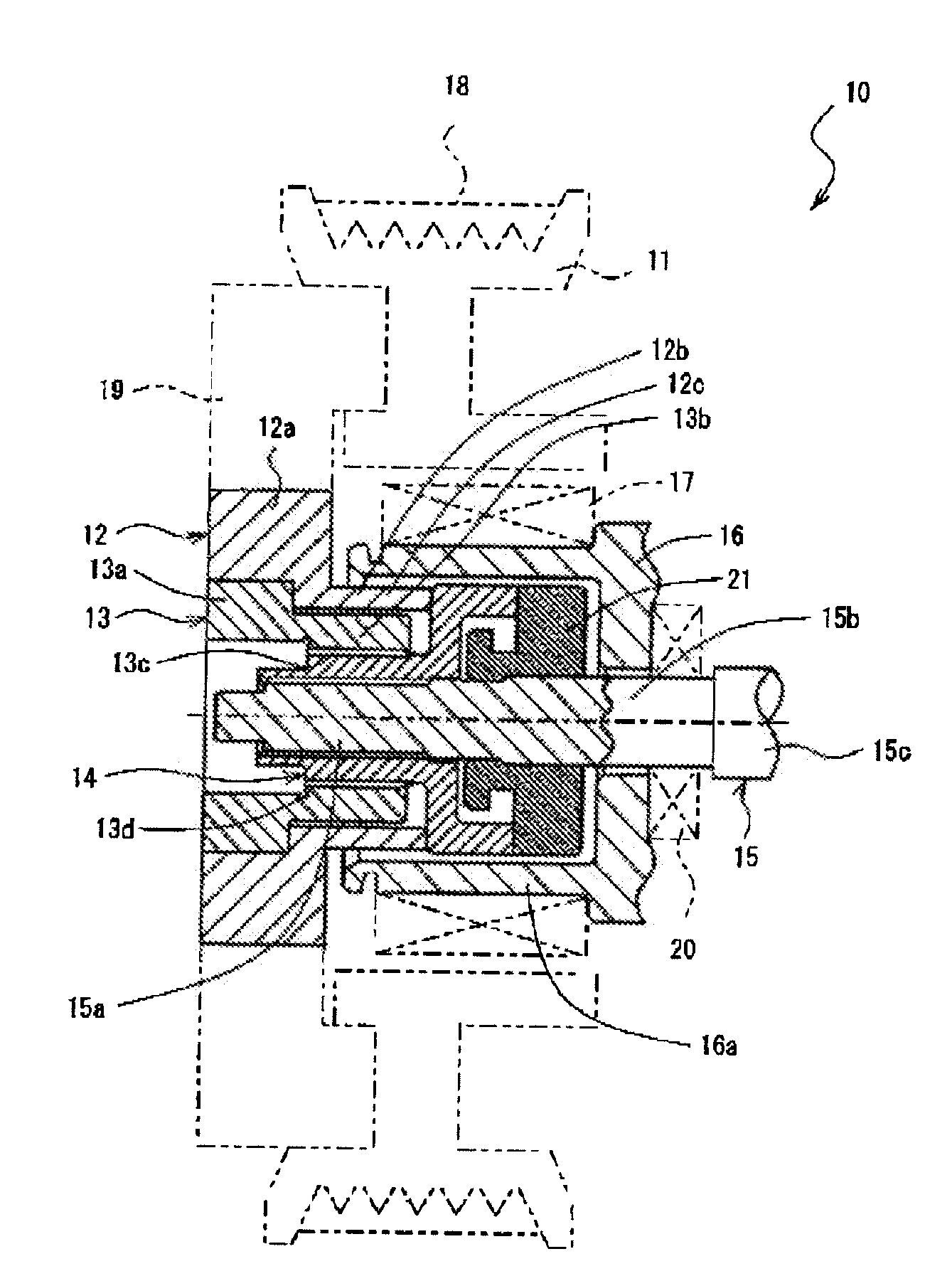
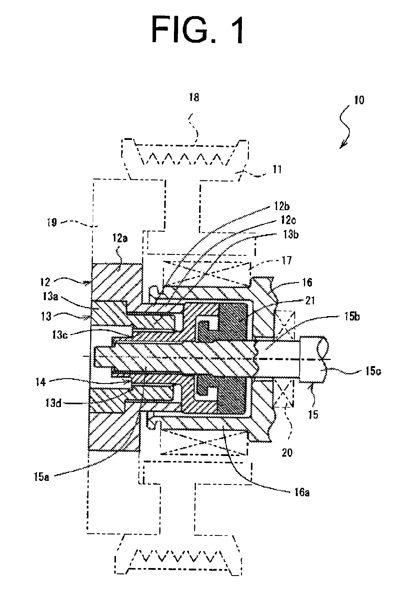
[0018]The following will describe a power transmission device of the compressor according to the present invention with reference to FIG. 1 through FIG. 5. As shown in FIG. 1, the power transmission device of the compressor of the first preferred embodiment is generally designated by reference numeral 10. The power transmission device 10 includes a pulley 11, a hub 12, a power shutoff member 13, a cylinder 14 and a casing 16 of the compressor. The power transmission device 10 is used for transmitting torque to the rotary shaft 15 from the pulley 11. The pulley 11 is rotatably mounted on the casing 16 of the compressor and driven by an engine and the like (not shown). The hub 12 is connected to the pulley 11 for rotation therewith. The power shutoff member 13 functioning as a torque limiter is interposed between the hub 12 and the rotary shaft 15.
[0019]The pulley 11 is rotatably mounted through a bearing 17 on a boss 16a which is provided at one end of the casing 16. A belt 18 is wou...
third embodiment
[0052]Referring to FIG. 7 showing a power transmission device 50 of the third embodiment according to the present invention, the power transmission device 50 includes a cylinder 51 having formed at the inner periphery thereof an internal thread portion 51a and screwed over the rotary shaft 15 through engagement between the internal thread portion 51a of the cylinder 51 and the external thread portion 15e of the rotary shaft 15. The cylinder 51 is further formed at the outer periphery thereof with an external thread portion 51b for engagement with the internal thread portion 13c of the power shutoff member 13. In addition, the cylinder 51 has a flange 51c extending radially outward and a projection 51d extending from a radially inner region of the flange 51c axially rearward of the compressor. The projection 51d has at the rear end thereof a cylinder-side contacting surface 51e for contact with the shaft-side seating surface 21a of the rotary shaft 15. The flange 51c has at the front...
PUM
 Abstract
Description
Claims
Application Information
 - R&D Engineer
- R&D Manager
- IP Professional
- Industry Leading Data Capabilities
- Powerful AI technology
- Patent DNA Extraction
Browse by: Latest US Patents, China's latest patents, Technical Efficacy Thesaurus, Application Domain, Technology Topic, Popular Technical Reports.
© 2024 PatSnap. All rights reserved.Legal|Privacy policy|Modern Slavery Act Transparency Statement|Sitemap|About US| Contact US: help@patsnap.com