Floor cleaning apparatus with elongate handle and handle extension

a technology of floor cleaning and extension handle, which is applied in the direction of vacuum cleaners, carpet cleaners, brushes, etc., can solve the problems of limited ability to clean beneath furniture, uncomfortable or difficult for some users, and difficult to achieve action in tight spaces

Inactive Publication Date: 2008-07-03
KWONNIE ELECTRICAL PRODS
View PDF7 Cites 26 Cited by
  • Summary
  • Abstract
  • Description
  • Claims
  • Application Information

AI Technical Summary

Benefits of technology

[0018]The hinge may allow the handle assembly to assume two extreme positions, where one position is the 180 degree position giving the equivalent to a normal straight handle, and the other is in the region of 90-135 degrees giving the whole handle approximately an L-shape.
[0003]With a handle of suitable length the user can maintain an upright stance using floor sweepers of this type for cleaning open floor areas, however while maintaining this stance the ability to clean beneath furniture is restricted. For instance, to sweep under a bed or sofa, the user must bend or kneel down until the handle is almost horizontal. This action is difficult to achieve in tight spaces, and may be uncomfortable or difficult for some users. Accordingly there is a need for an improved floor cleaning device such as a sweeper, that allows the user quickly and easily can clean under furniture.

Problems solved by technology

With a handle of suitable length the user can maintain an upright stance using floor sweepers of this type for cleaning open floor areas, however while maintaining this stance the ability to clean beneath furniture is restricted.
This action is difficult to achieve in tight spaces, and may be uncomfortable or difficult for some users.

Method used


Image

  • Floor cleaning apparatus with elongate handle and handle extension
  • Floor cleaning apparatus with elongate handle and handle extension
  • Floor cleaning apparatus with elongate handle and handle extension

Examples


Embodiment Construction

[0025]Referring now to the drawings, which illustrate the preferred embodiment of the invention only and not intended to limit the same; we shall first clarify the parts and then the function.

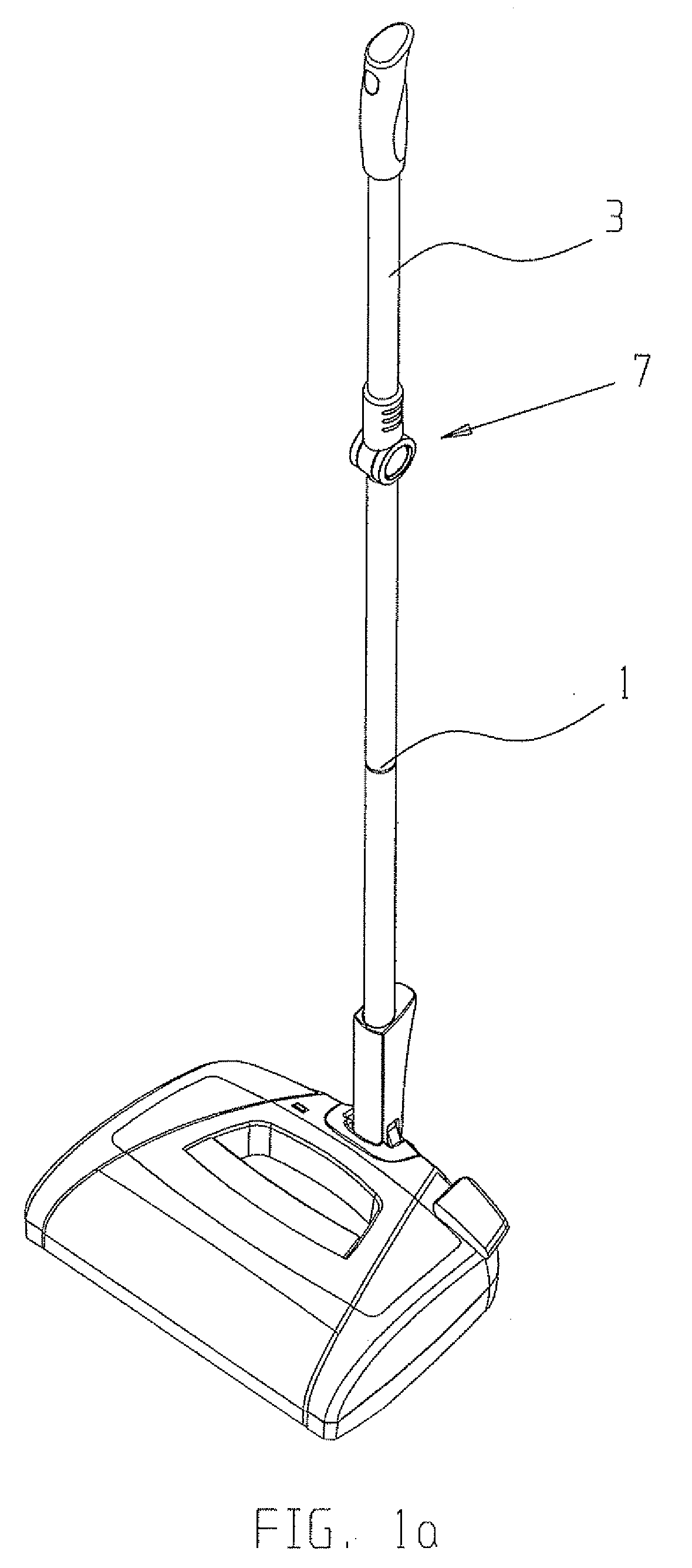
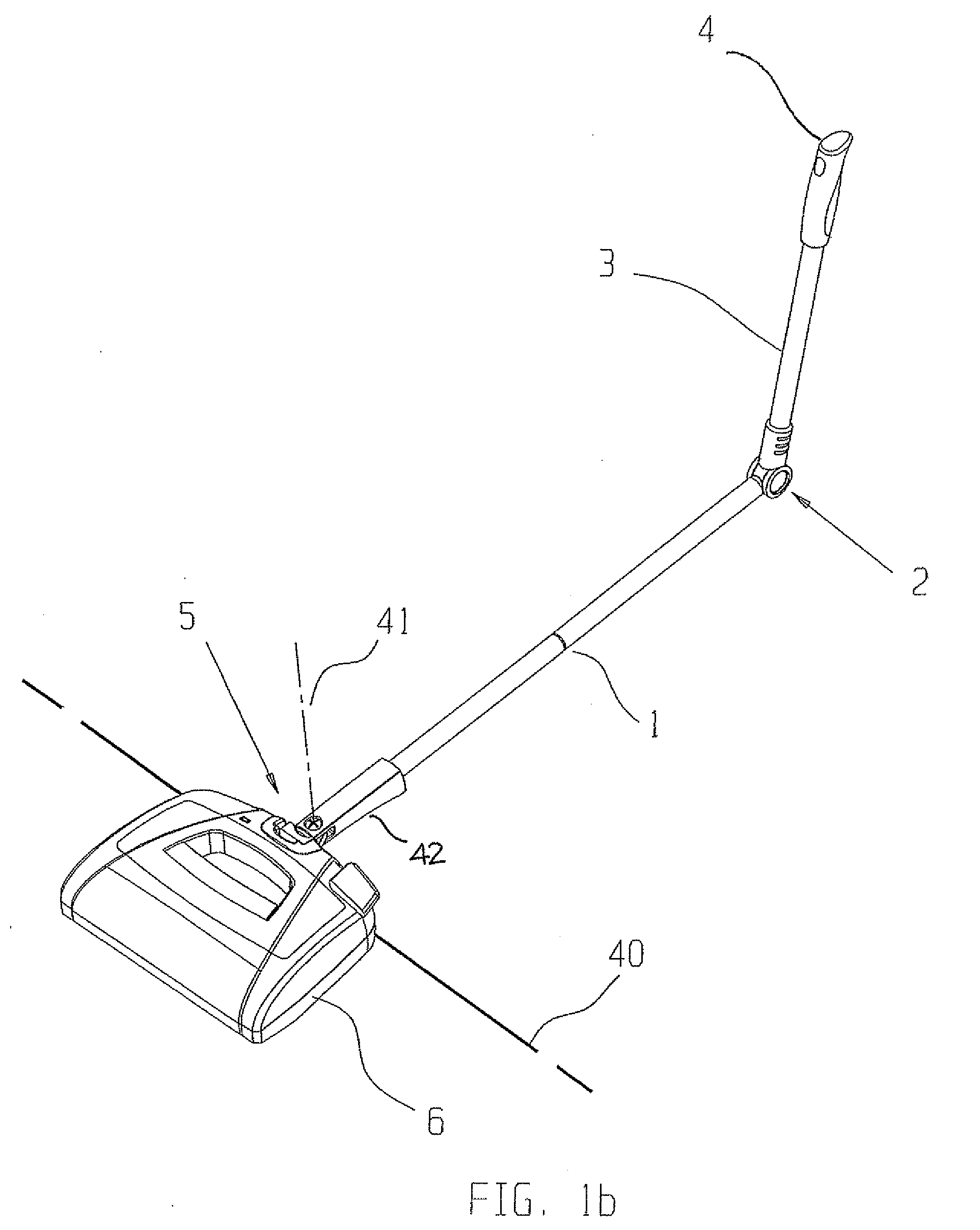
[0026]FIGS. 1a and 1b illustrates a sweeper in first and second operating configurations respectively. The sweeper includes a cleaning head 6 and a handle assembly 7. The handle assembly 7 includes an elongate handle 1 connected at its inner end by a pivoting steering joint 5 to the cleaning head 6, and at its outer end by a hinge 2 to an elongate handle extension 3. The terms “inner” and “outer” refer respectively to the longitudinally opposing ends closest to, and farthest from the attachment to the cleaning head. The handle 1 is approximately twice the length of the handle extension 3. A grip 4 is provided on the outer end of the handle extension 3. In the first configuration (FIG. 1a) the handle assembly 7 is shown configured for normal use, with the handle 1 and handle extension 3 aligned ...


PUM


Abstract

A floor sweeping apparatus comprises a cleaning head with an elongate handle fixed at an inner end by a pivoting joint to the cleaning head, and at an outer end by a hinge to an elongate handle extension. A locking mechanism allows the handle extension to be locked in different angular positions relative to the handle and can be remotely controlled from the handle extension.

Description

TECHNICAL FIELD[0001]The present invention relates to domestic appliances and more specifically floor-care equipment such as, but not limited to, sweepers.BACKGROUND[0002]A common modern floor sweeper has a cleaning head to which an elongate handle is mounted, the cleaning head holding at least one motorized rotating brush for sweeping debris from the floor, and a receptacle for collecting the debris. The handle is typically an elongate tubular member, comprising one or more predominantly straight sections, with a handgrip attached at its outer end. The handle is normally connected to the cleaning head via a pivoting or universal joint and some joint designs permit steering of the cleaning head by twisting the handle.[0003]With a handle of suitable length the user can maintain an upright stance using floor sweepers of this type for cleaning open floor areas, however while maintaining this stance the ability to clean beneath furniture is restricted. For instance, to sweep under a bed...

Claims


Application Information

Patent Timeline
Patent Type & Authority Applications(United States)
IPC IPC(8): B25G1/06
CPCA47L9/242
Inventor PANG, KWOK FUNG
Owner KWONNIE ELECTRICAL PRODS
Why Eureka
Try Eureka