Multi-dimensional paver edging

a multi-dimensional, paver technology, applied in the field of land use, can solve the problems of limiting the angle to which the edger can be bent, prior art edgers that cannot be produced to accommodate standard-size pavers, and edging fails to provide the stability of l-shaped edging in either a linear or contoured arrangement, so as to prevent debris interference

Inactive Publication Date: 2008-07-10
SUNCAST
View PDF9 Cites 43 Cited by
  • Summary
  • Abstract
  • Description
  • Claims
  • Application Information

AI Technical Summary

Benefits of technology

[0019]Yet another objective of the invention is to provide a tab member that includes contoured edges allowing at least 90 degree bends without interference between the edges of the tabs or debris between the tabs.

Problems solved by technology

However, edgers known in the prior art provided with these horizontal extending flanges or flaps have been designed so that the flange prevents bending of the strip or the flaps interfere with one another when the strip is bent, thereby limiting the angle to which the edger can be bent.
Prior art edgers have also not been produced to accommodate standard size pavers when the strips are bent, but rely on the pavers being cut to provide a snug fit.
This type of edging fails to provide the stability of L-shaped edging in either a linear or contoured arrangement.
A drawback to this kind of arrangement is that during frost heaving the stake is driven up out of the ground, and since the stake is securely interlocked with the strip, the strip is also dislodged from the ground.
However, the device is limited to linear sections making the device unsuitable for use around contoured paver layouts and the like.
While this device is particularly suited for contoured layouts, the numerous pivotal connections make linear sections of edging difficult to install.
While these devices are generally suitable for their intended purpose, they include various drawbacks that have not been entirely addressed by the prior art.
For example, the construction of the tabs used for securing the edging to the ground surface do not permit 90° bends without overlapping of the tabs.
Abutting the tabs is often difficult due to the sand and other debris associated with landscaping and most particularly with installing pavers.
In addition, these devices do not include a rear rail that substantially prevents bending of the edging for improved linear paver layouts.
In addition, none of the devices include material reducing apertures to save in usage of raw materials during formation of the edging strips.

Method used


Image

  • Multi-dimensional paver edging
  • Multi-dimensional paver edging
  • Multi-dimensional paver edging

Examples


Embodiment Construction

[0029]While the present invention is susceptible of embodiment in various forms, there is shown in the drawings and will hereinafter be described a presently preferred embodiment with the understanding that the present disclosure is to be considered an exemplification of the invention and is not intended to limit the invention to the specific embodiments illustrated.

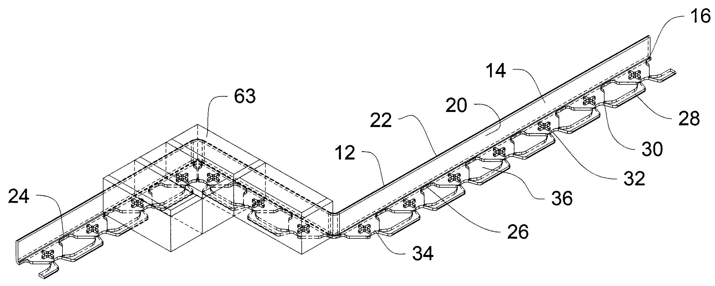
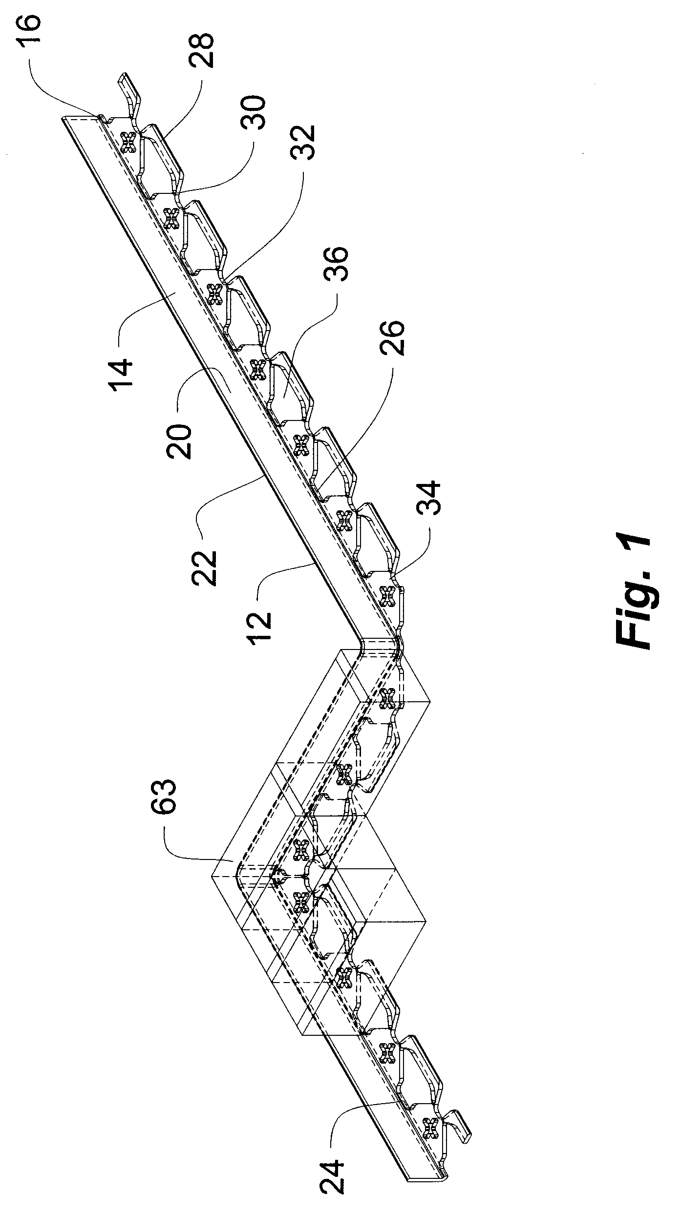
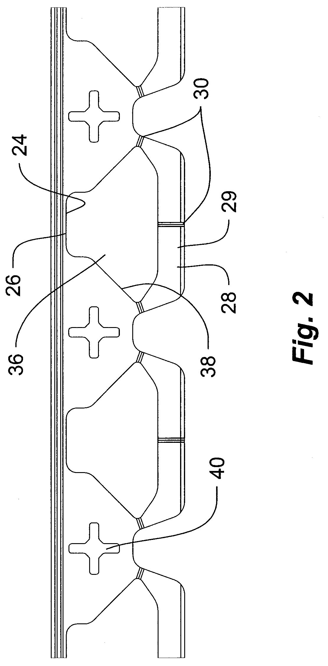
[0030]In referring to the drawings, like numerals refer to like parts. A preferred embodiment of a paver edging device 10 embodying the subject invention is shown in FIGS. 1-6 and includes an elongate strip portion 12 having a substantially planar portion 14, a first edge 16, a second opposed edge 18, and wherein planar portion 14 includes opposed sides 20 and 22. In one embodiment the elongate strip portion 12 includes spaced, longitudinal strengthening ribs (not shown) integrally formed therewith and extending along the full length of strip 12 to provide additional strength to the elongate portion. The paver edger 10 i...


PUM


Abstract

Among the several aspects and features of the present invention may be noted the provision of a paver edging device for use as an interface or boundary of a paved region. In one aspect the edging device includes an elongate strip extending in a longitudinal direction having a flange portion integrally formed to an edge of the elongate strip and extending in a transverse direction outwardly from one side of the strip. The flange is provided with a series of contoured-V cut-out portions having contoured edges. The contoured-V cut-out portions are connected along the rear edge thereof with a plurality of rear rail segments. Bending or contouring of the strip therefore requires removal of a portion of the rear rail segments.

Description

FIELD OF THE INVENTION[0001]This invention relates generally to landscaping, and more specifically to a paver edging strip formed by the process of injection molding from a suitable plastic material for use as an interface or boundary between a paver bricked area and other types of terrain.BACKGROUND OF THE INVENTION[0002]The need for paver edging devices to separate paved areas from different kinds of terrain is well known. There are several basic types of brick edging devices utilized for a similar application, namely edging grassy areas. One type includes a single upright elongate strip with a horizontal flange member or a plurality of discrete individual flap members extending away from the elongate strip to provide support for the strip or an anchoring base for the device. However, edgers known in the prior art provided with these horizontal extending flanges or flaps have been designed so that the flange prevents bending of the strip or the flaps interfere with one another whe...

Claims


Application Information

Patent Timeline
Patent Type & Authority Applications(United States)
IPC IPC(8): A01G1/08E02D27/00A01G9/28
CPCE01C11/221A01G1/08A01G9/28
Inventor BELLA, JOE
Owner SUNCAST
Why Eureka
Try Eureka