[0015]The various embodiments of the present disclosure and their advantages are best understood by referring to FIGS. 1 through 5 of the drawings. The elements of the drawings are not necessarily to scale, emphasis instead being placed upon clearly illustrating the principles of the disclosure. Throughout the drawings, like numerals are used for like and corresponding parts of the various drawings.
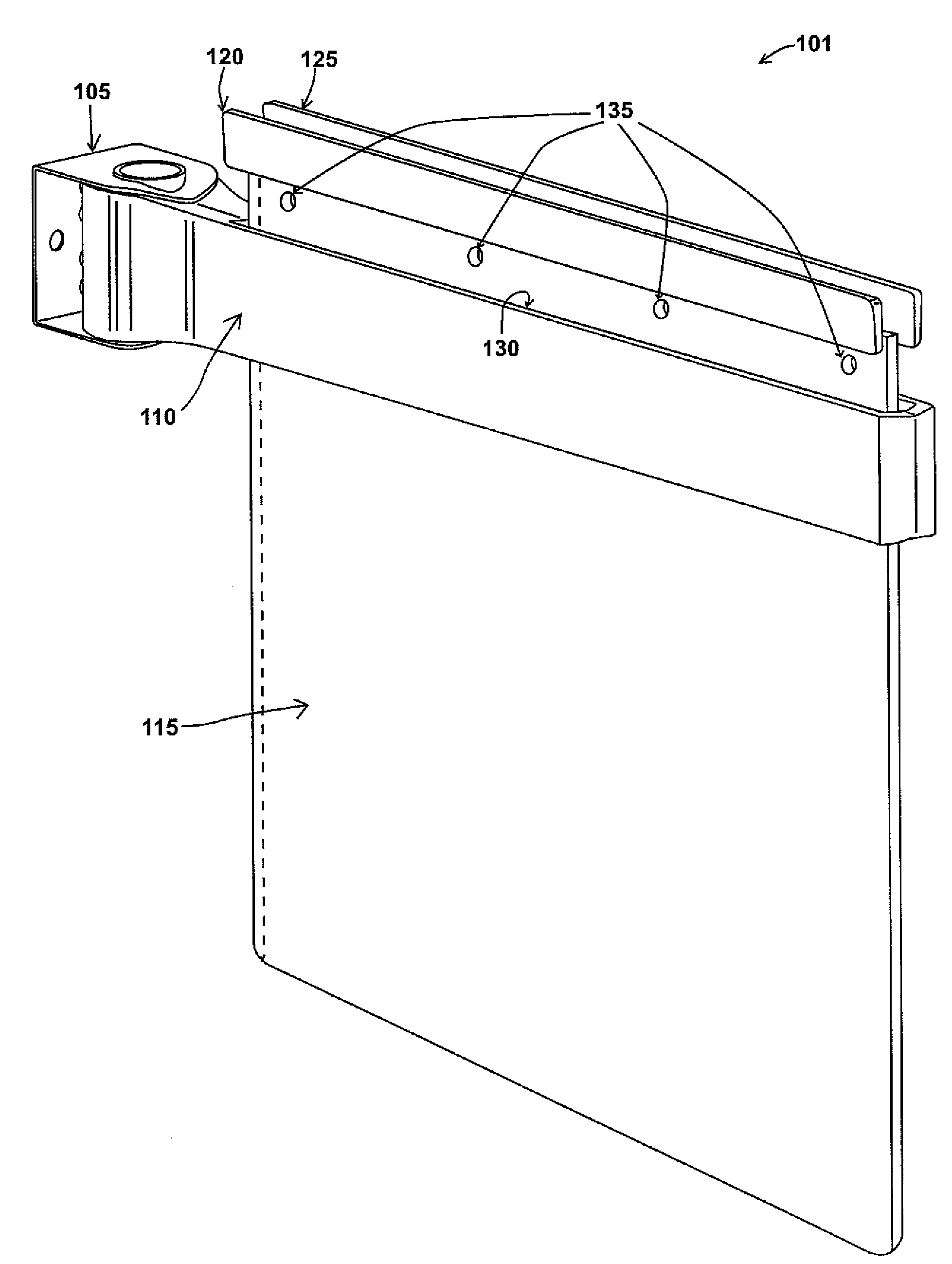
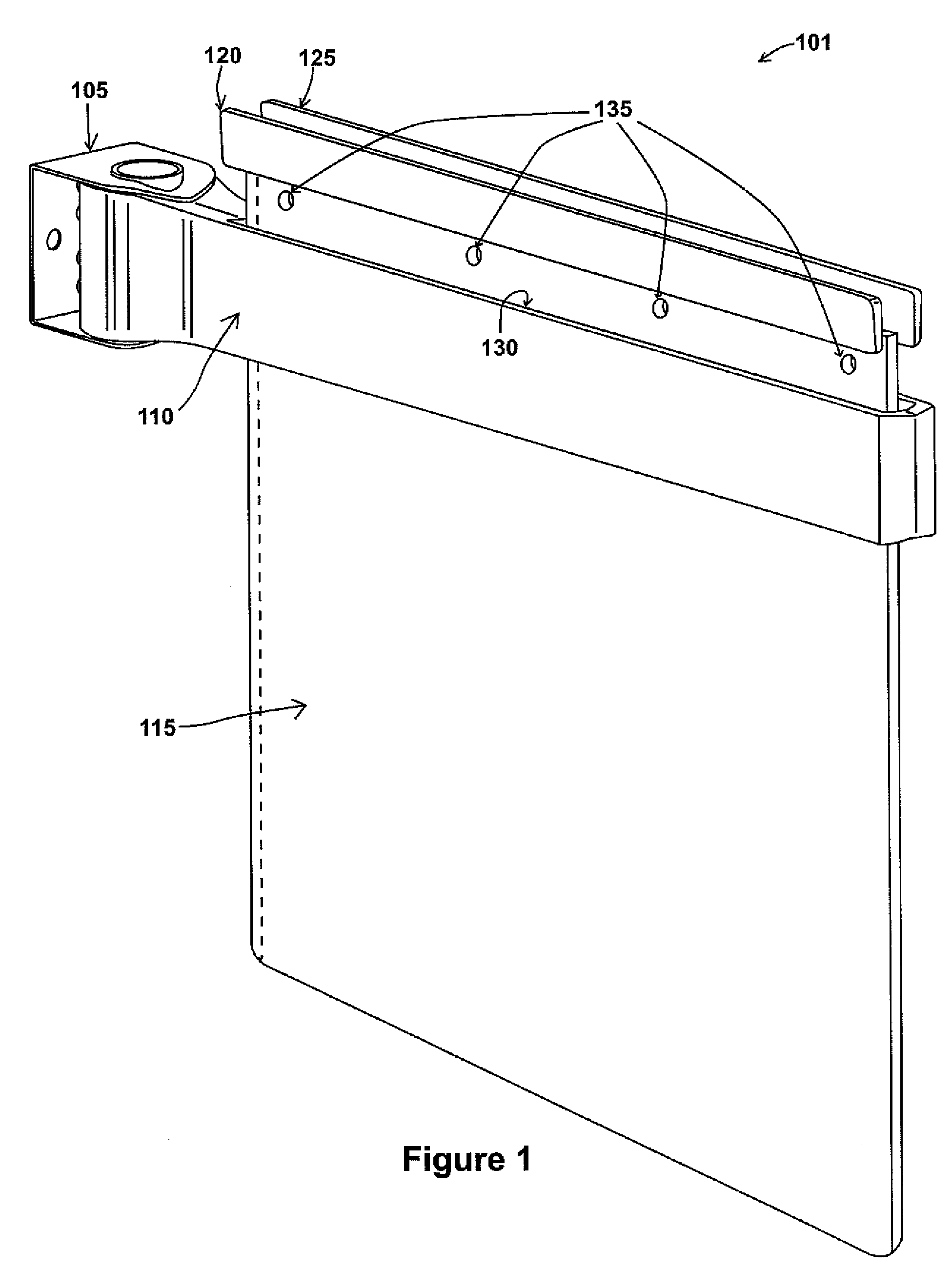
[0016]Referring now to FIG. 1, a mudflap assembly 101 comprises a bracket 105, a hanger 110, a mudflap 115, and two mudflap retainers 120, 125. The bracket 105 attaches to a vehicle (not shown) behind its wheel (not shown). A hanger 110 couples to the bracket 105 and extends away from the vehicle (not shown) in order to retain a mudflap 115 in a position to deflect flying debris (not shown). The mudflap 115 is coupled to the hanger 110 by two retainers 120, 125, wherein each retainer has a plurality of protrusions (FIGS. 3, 4, 5) which extend through the holes 135 of the mudflap 115. The protrusions of the retainers join together through the holes 135 of the mudflap 115 creating a wedge at the top of the mudflap (FIG. 2). The mudflap 115 can then be inserted through a slot 130 in the hanger 110 wherein the wedge created by the retainers couples with the crevice formed in the slot 130 of the hanger 110.
[0017]Referring now to FIG. 2, the inner surfaces 205, 210 of the slot (FIG. 1) form a V-shaped crevice upon which the retainers 120, 125 rest. In this way, the mudflap 115 is retained within the hanger 110, without the need for bolts or other fasteners.
[0018]FIGS. 3, 4, and 5 show the side, top, and front views, respectively, of a mudflap retainer 120. Referring now to FIGS. 3-5, a plurality of protrusions 305, 310 are located on the inner wall 340 (FIG. 5), and are spaced such that they match the standard holes 135 (FIG. 1) on the mudflap 115 (FIG. 1). When the inner wall 340 of two retainers 120, 125 (FIG. 1) face each other, the protrusions 305 mate with the protrusions 310 similar to a male/female connection. In other embodiments, other means of attaching the retainers together through the mudflap, such as snaps, buttons, screws, and bolts are possible with or without such protrusions. Furthermore, the two retainers do not have to be separate halves. They may be hinged together at the top such that they clamp down onto the mudflap.
[0019]As shown in FIG. 5, in one embodiment the profile of the retainer creates a wedge sufficient to couple with the inner surfaces 205, 210 (FIG. 2) of the slot 130 (FIG. 1) of the hanger 110 (FIG. 1). Accordingly, the top edge 315 of the retainer 120 is wider than the bottom edge 320. In other embodiments, the profile of the retainer may resemble other shapes (square, rectangular, circular) sufficient to fit within the top of the slot 130 (FIG. 1) of the hanger, yet not pass through the bottom of the slot 130 (FIG. 1). In this regard, the profile of the retainer will match the shape of the crevice formed by the inner surfaces of the slot of the hanger.
[0020]This disclosure may be provided in other specific forms and embodiments without departing from the essential characteristics as described herein. The embodiments described above are to be considered in all aspects as illustrative only and not restrictive in any manner. The following claims rather than the foregoing description indicate the scope of the disclosure.
[0021]As described above and shown in the associated drawings, the present disclosure comprises a mudflap retainer. While particular embodiments of the disclosure have been described, it will be understood, however, that the disclosure is not limited thereto, since modifications may be made by those skilled in the art, particularly in light of the foregoing teachings. It is, therefore, contemplated by the appended claims to cover any such modifications that incorporate those features or those improvements that embody the spirit and scope of the present disclosure.