Bare Floor Cleaner

a technology for cleaning bare floors and cleaning brushes, which is applied in the direction of suction cleaners, suction handles, domestic applications, etc., can solve the problems of inconvenient movement, difficult to transfer the entire pile, and a portion of the pile tending to remain on the floor

Active Publication Date: 2008-08-14
BISSELL INC
View PDF11 Cites 38 Cited by
  • Summary
  • Abstract
  • Description
  • Claims
  • Application Information

AI Technical Summary

Benefits of technology

[0012]A wet / dry bare floor cleaner according to the invention comprises a base; a handle pivotally connected to the base; a recovery system comprising a wet suction nozzle, a dry suction nozzle, a recovery tank for receiving wet and dry debris, a working air conduit extending from each of the dry suction nozzle and the wet suction nozzle to the recovery tank, a motor / fan assembly mounted to one of the handle and the base and adapted to create a working air flow in the working air conduit from at least one of the dry suction nozzle and the wet nozzle and to the recovery tank, and a diverter mounted in the working air conduit and movable between a dry suction position and a wet suction position for selectively at least partially blocking working air flow from the wet suction nozzle and the dry suction nozzle, respectively, to the recovery tank; and the improvement comprising an actuator mounted to the handle and connected to the diverter to move the diverter between the dry suction position and the wet suction position.

Problems solved by technology

However, when sweeping dirt from a pile into the dustpan, it is difficult to transfer the entire pile, and, as a result, a portion of the pile tends to remain on the floor.
Such motion can be inconvenient, difficult, and even painful for some users.
Dust cloths can also be used, but large dirt particles do not sufficiently adhere thereto.
Another option is vacuuming the dry dirt, but most homes are equipped with vacuum cleaners that are designed for use on carpets and can damage bare surfaces.
Each time, the mop is usually placed in the same bucket, and after several repetitions, the cleaning solution becomes dirty and cold.
Furthermore, movement of the mop requires physical exertion, and the mop head wears with use and must be replaced periodically.
Additionally, cloths are not as absorbent as mops and, therefore, can leave more soiled cleaning solution on the floor.
Others are capable of performing all functions without accessories but have complex designs and features that can be difficult and confusing to operate.

Method used


Image

  • Bare Floor Cleaner
  • Bare Floor Cleaner
  • Bare Floor Cleaner

Examples


Embodiment Construction

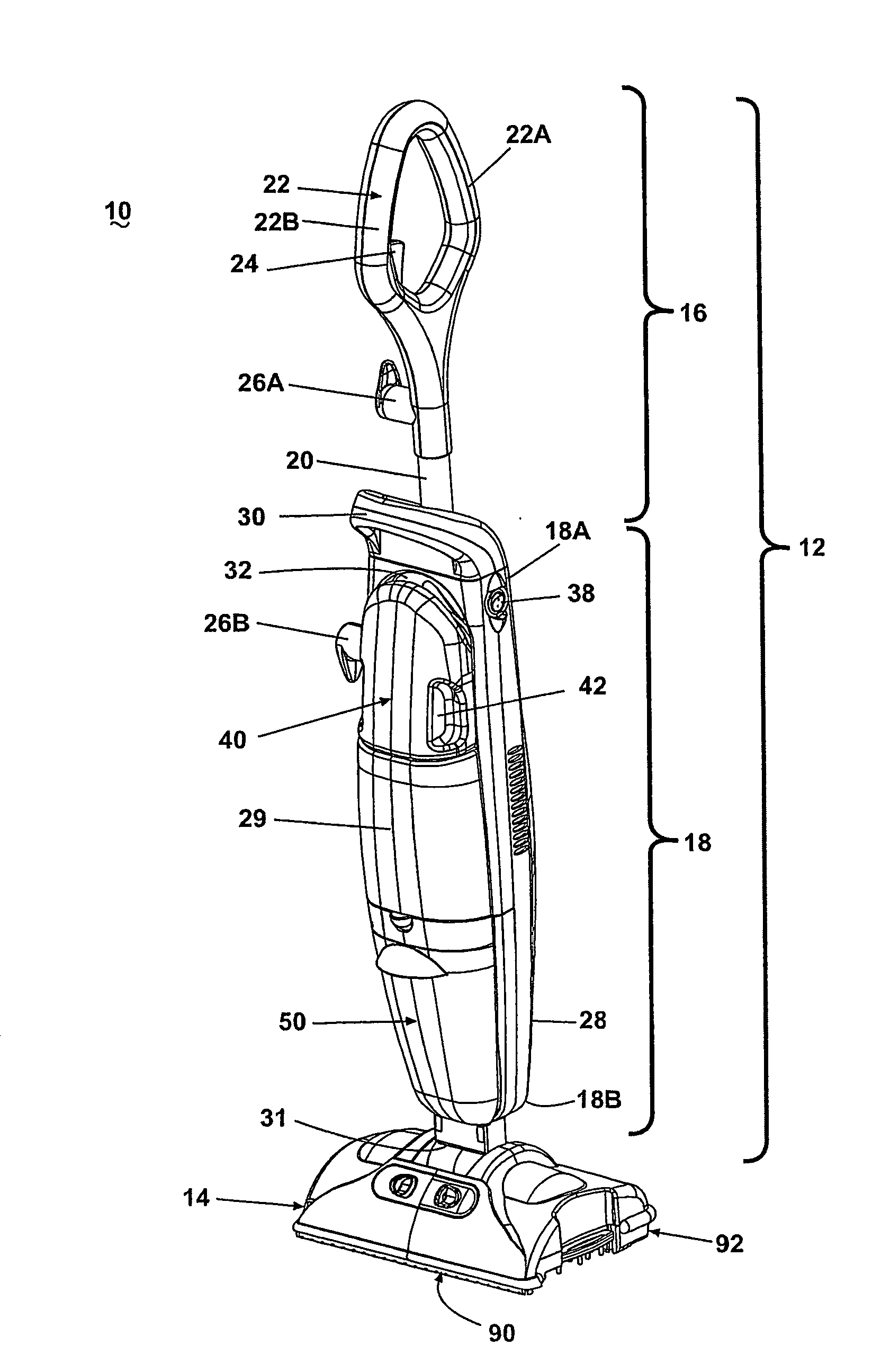
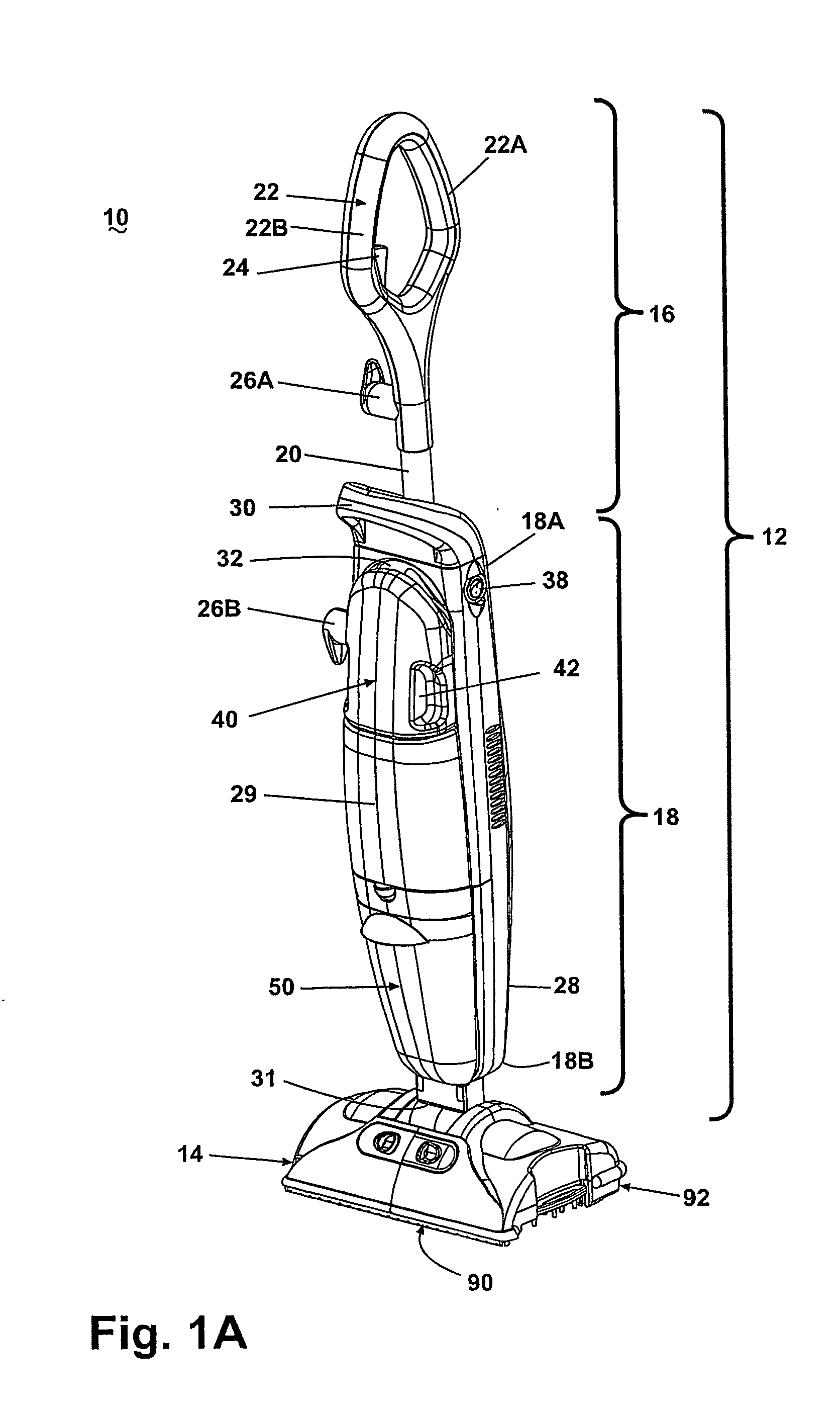
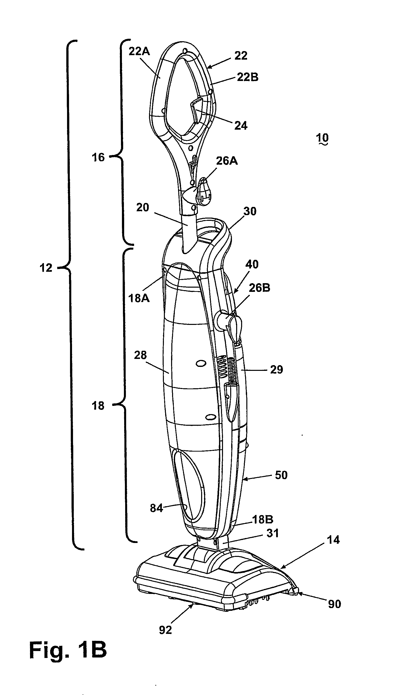
[0065]Referring to the drawings and to FIGS. 1A, 1B, 2A, and 2B in particular, a wet / dry bare floor cleaner 10 according to the invention comprises a handle assembly 12 pivotally mounted to a base or foot assembly 14. The handle assembly 12 can pivot from an upright, vertical position, as shown in FIGS. 1A and 1B, wherein the handle is substantially vertical relative to the surface to be cleaned, to either direction relative to the foot assembly 14. In particular, the handle assembly 12 can pivot to a first position forward of the upright position, as shown in FIG. 2A, or to a second position rearward of the vertical position, as illustrated in FIG. 2B.

[0066]Referring additionally to FIGS. 3 and 4, the handle assembly 12 comprises an upper handle 16 and a lower handle 18, and the upper handle 16 comprises a hollow tube 20 with an upper end 20A and a lower end 20B. A bi-directional grip 22 is fixedly attached to the upper end 20A of the tube 20; however, it is within the scope of the...


PUM


Abstract

A bare floor cleaner for wet and dry bare floor surfaces comprises a base with wet and dry suction nozzles and a handle pivotally connected to the base. A diverter mounted in the working air conduit between each of the dry suction nozzle and the wet suction nozzle to a recovery tank is movable by movement of the handle between a dry suction position and a wet suction position for selectively at least partially blocking working air flow from the wet suction nozzle and the dry suction nozzle, respectively, to the recovery tank.

Description

CROSS-REFERENCE TO RELATED APPLICATION[0001]This application claims the benefit of U.S. provisional application Ser. No. 60 / 481,277, filed Aug. 22, 2003, and U.S. provisional application Ser. No. 60 / 521,253, filed Mar. 19, 2004, which are incorporated herein in their entirety.BACKGROUND OF THE INVENTION[0002]1. Field of the Invention[0003]The invention relates to wet and dry cleaning of bare floor surfaces. In one aspect, the invention relates to a bare floor cleaner that performs both wet and dry pickup. In another aspect, the invention relates to a bare floor cleaner that selectively performs wet and dry floor cleaning functions by convenient movement of a manipulating handle. In yet another aspect, the invention relates to a bare floor cleaner having a diverter for selectively blocking one of a wet nozzle opening and dry nozzle opening, wherein the diverter is actuated by movement of a handle assembly.[0004]2. Description of the Related Art[0005]The common procedure of cleaning a...

Claims


Application Information

Patent Timeline
Patent Type & Authority Applications(United States)
IPC IPC(8): A47L7/00A47L5/30A47L9/04A47L9/02A47L9/06A47L9/32
CPCA47L7/0028A47L7/0042A47L9/02A47L9/04A47L9/325A47L9/0653A47L9/0666A47L9/0673A47L9/06A47L5/30A47L7/00
Inventor JANSEN, JOHN L.
Owner BISSELL INC
Why Eureka
Try Eureka