Fire ant colony killer

a technology of ant colony and killer, which is applied in the field of fire ant colony killer, can solve the problems of causing environmental and health concerns, often ineffective chemical treatments, and always hurting ant bites, and achieving the effects of reducing the number of ants killed

Inactive Publication Date: 2008-08-21
MCDONALD KEN
View PDF10 Cites 5 Cited by
  • Summary
  • Abstract
  • Description
  • Claims
  • Application Information

AI Technical Summary

Benefits of technology

[0017]The method and apparatus as described above further comprising means for manually lowering and raising the applicator.
[0018]The met

Problems solved by technology

These chemical treatments are often ineffective and always create environmental and health concerns.
Fire ants, in particular, are very aggressive and their bites are always

Method used


Image

  • Fire ant colony killer
  • Fire ant colony killer
  • Fire ant colony killer

Examples


Embodiment Construction

[0022]Whilst the making and using of various embodiments of the present invention are discussed in detail below, it should be appreciated that the present invention provides many applicable inventive concepts, which can be embodied in a wide variety of specific contexts. The specific embodiments discussed herein are merely illustrative of specific ways to make and use the invention and do not limit the scope of the invention. Moreover, the present invention, while described for the extermination of fire ants and fire ant colonies, may be utilized to exterminate a wide variety of insects.

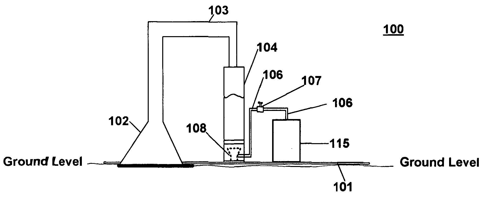
[0023]Referring now to FIG. 1, a side, cross-sectional view of the mechanized exterminator 100 is depicted. The apparatus is affixed to a base 101. The base 101 is made of durable material, such as steel, for example, and may be of any size, depending on the size of the apparatus to be secured on it. It will be appreciated that any suitable material may be used for the base 101. In the instant embodi...


PUM


Abstract

A mechanized system for exterminating and several embodiments thereof are presented. Steam is generated and transported to a movable applicator. The applicator is positioned over a designated area of ground and the steam is applied exterminating the insects on and/or under the designated area of ground.

Description

BACKGROUND OF THE INVENTIONDescription of the Related Art[0001]Insect extermination, particularly for undesirable external insects, has been largely confined to chemical treatments. Zappers are used for certain flying insects. These chemical treatments are often ineffective and always create environmental and health concerns.[0002]Fire ants, in particular, are very aggressive and their bites are always hurtful and sometimes dangerous. The usual result from a chemical treatment is that the colony relocates. Often, they become even more aggressive as a result.[0003]One treatment often employed to exterminate fire ants is to pour boiling water on the colony bed. However, this treatment is often only partially effective and rarely kills the queen ants. Fire ants prepare an elaborate system of tunnels to get from the nest to the ground surface. The boiling water has the effect of collapsing these tunnels and thus shielding ants below from harm.[0004]Thus, there is a need in the art for a...

Claims


Application Information

Patent Timeline
IPC IPC(8): A01M19/00A01M1/20
CPCA01M3/007
Inventor MCDONALD, KEN
Owner MCDONALD KEN
Why Eureka
Try Eureka