Folding head restraint mechanism

a head restraint and folding technology, applied in the field of adjustable head restraints, can solve the problems of high cost and complicated mechanism of folding

Inactive Publication Date: 2008-08-28
LEAR CORP
View PDF17 Cites 56 Cited by
  • Summary
  • Abstract
  • Description
  • Claims
  • Application Information

AI Technical Summary

Benefits of technology

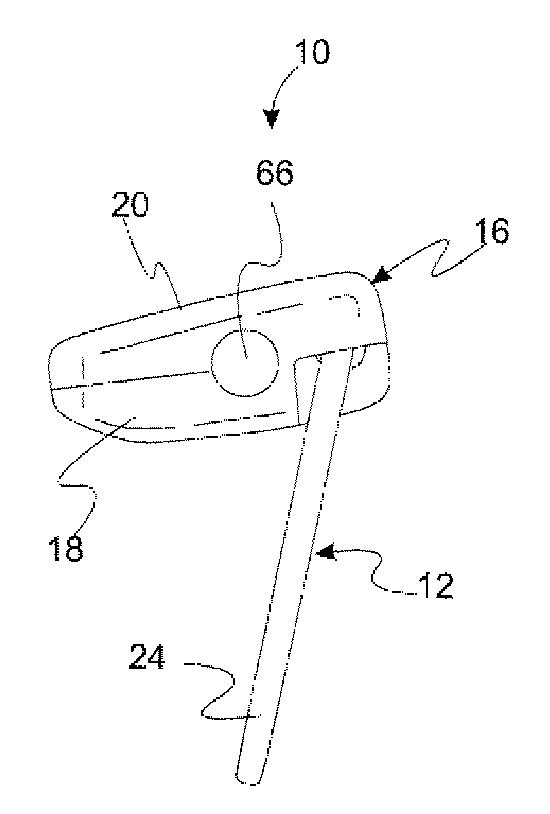
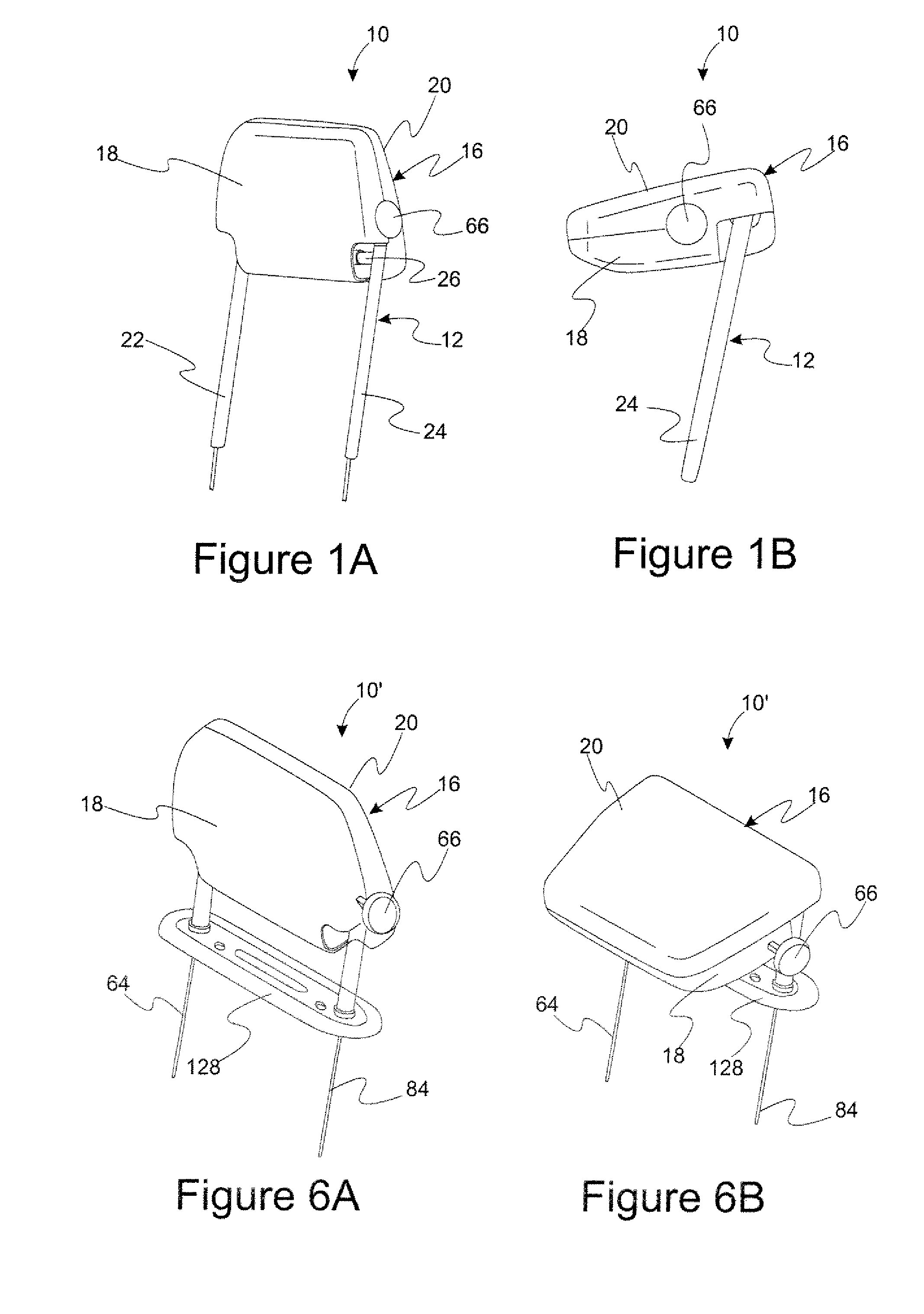
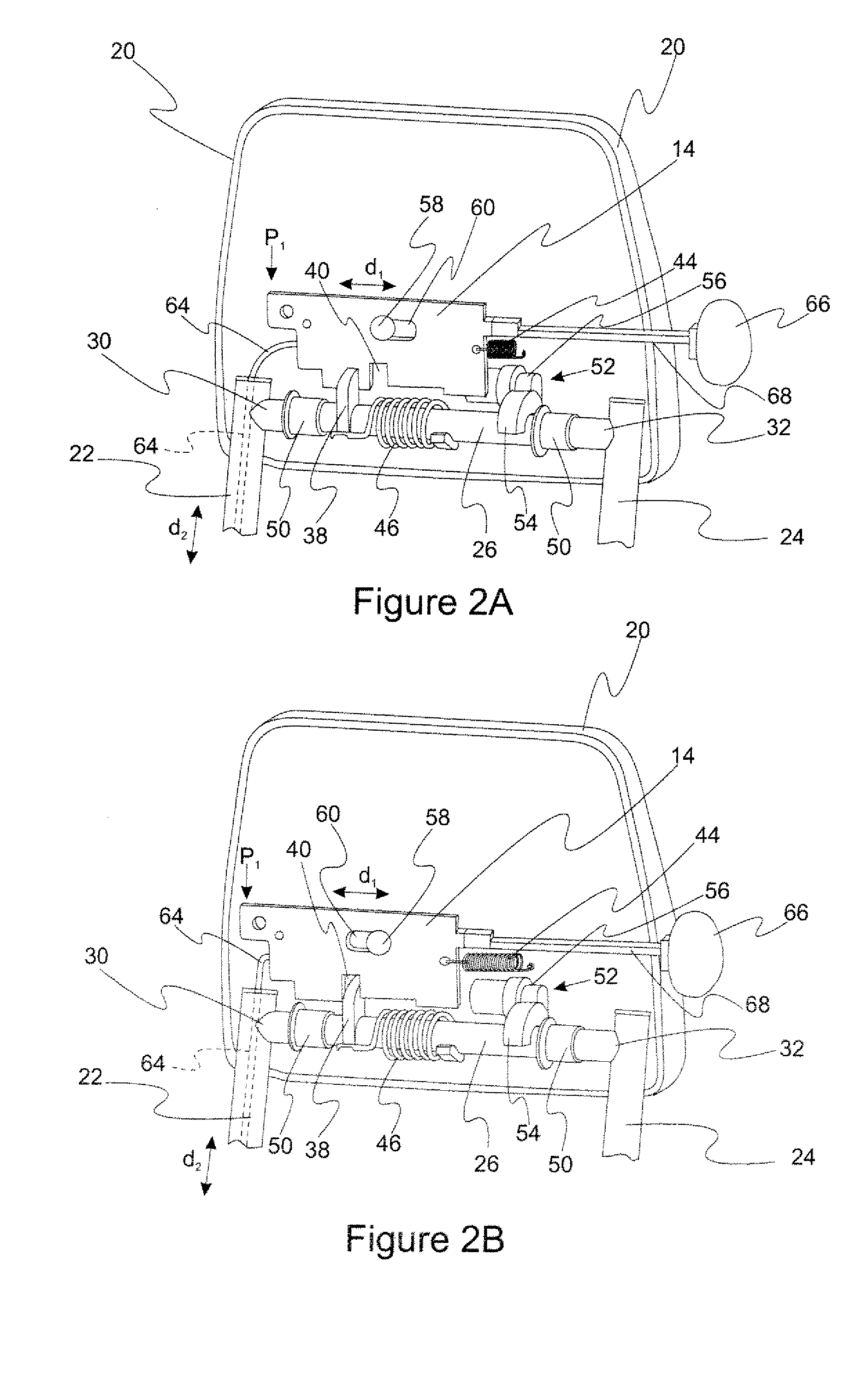
[0007]The present invention solves one or more problems of the prior art by providing in at least one embodiment a foldable head restraint assembly that is moveable from a first head restraint position to a second head restraint position. The head restraint assembly includes a mounting subassembly, a structural shell, and a locking plate. The structural shell is supported by the mounting subassembly. The mounting subassembly includes a first support post, a second support post, a cross member and a latch. The cross member has a first end attached to the first support post and a second end attached to the second support post. Moreover, the latch is attached to the cross member. The folding motion of the head restraint is initiated by movement of the locking plate. The locking plate is positionable at a first plate position for engaging the latch and at a second plate position for releasing the latch. Advantageously, the structural shell is pivotable about the mounting subassembly when the latch plate is in the second plate position.

Problems solved by technology

Although these head restraints of the prior art work reasonably well, the mechanism for folding tend to be complicated and expensive.

Method used


Image

  • Folding head restraint mechanism
  • Folding head restraint mechanism
  • Folding head restraint mechanism

Examples


Embodiment Construction

)

[0019]Reference will now be made in detail to presently preferred compositions, embodiments and methods of the present invention, which constitute the best modes of practicing the invention presently known to the inventors. The figures are not necessarily to scale. However, it is to be understood that the disclosed embodiments are merely exemplary of the invention that may be embodied in various and alternative forms. Therefore, specific details disclosed herein are not to be interpreted as limiting, but merely as a representative basis for any aspect of the invention and / or as a representative basis for teaching one skilled in the art to variously employ the present invention.

[0020]Except in the examples, or where otherwise expressly indicated, all numerical quantities in this description indicating amounts of material or conditions of reaction and / or use are to be understood as modified by the word “about” in describing the broadest scope of the invention.

[0021]It is also to be u...


PUM


Abstract

A foldable head restraint assembly includes a mounting subassembly, a structural shell, and a locking plate. The mounting subassembly supports the structural shell and includes a first support post, a second support post, a cross member, and a latch rigidly. The cross member is attached to the first and second support posts and to the latch. The folding motion of the head restraint is initiated by movement of the locking plate which is positionable at a first plate position for engaging the latch and at a second plate position for releasing the latch. The structural shell is pivotable about the mounting subassembly when the latch plate is in the second plate position

Description

BACKGROUND OF THE INVENTION[0001]1. Field of the Invention[0002]The invention relates to head restraints for vehicle seats, more particularly to adjustable head restraints.[0003]2. Background Art[0004]Adjustable head restraints for vehicle seats are provided for comfort and safety of an occupant. For example, U.S. Pat. No. 6,631,956 B2, which issued on Oct. 14, 2003, discloses an adjustable head restraint with a rod that supports the head restraint and translates relative to sleeves of the seatback.[0005]Another offering of the prior art is a head restraint that is adjustable on posts that extend from the seatback. The posts are received within receptacles of the seatback and the posts are also adjustable relative to the receptacles. The head restraint includes a detent mechanism for maintaining a position of the head restraint relative to the posts; and the receptacles include a locking mechanism for locking the posts relative to the receptacles. Moreover, some variations of the pr...

Claims


Application Information

Patent Timeline
Patent Type & Authority Applications(United States)
IPC IPC(8): A47C7/38
CPCB60N2/4855B60N2/856B60N2/859
Inventor JAMMALAMADAKA, SAI PRASADYETUKURI, ARJUN V.LOCKE, GERALD S.
Owner LEAR CORP
Why Eureka
Try Eureka