Connector pin assembly

Inactive Publication Date: 2008-09-04
CUI KAN
View PDF15 Cites 68 Cited by
  • Summary
  • Abstract
  • Description
  • Claims
  • Application Information

AI Technical Summary

Benefits of technology

[0008]The connector pin assembly releasably retains telescoped excavating support and wear members in their telescoped relationship. The connector pin assembly is removably received in aligned connector openings in the members. A body portion of th

Problems solved by technology

The aforementioned configuration undergoes substantial wear such

Method used


Image

  • Connector pin assembly
  • Connector pin assembly
  • Connector pin assembly

Examples


Embodiment Construction

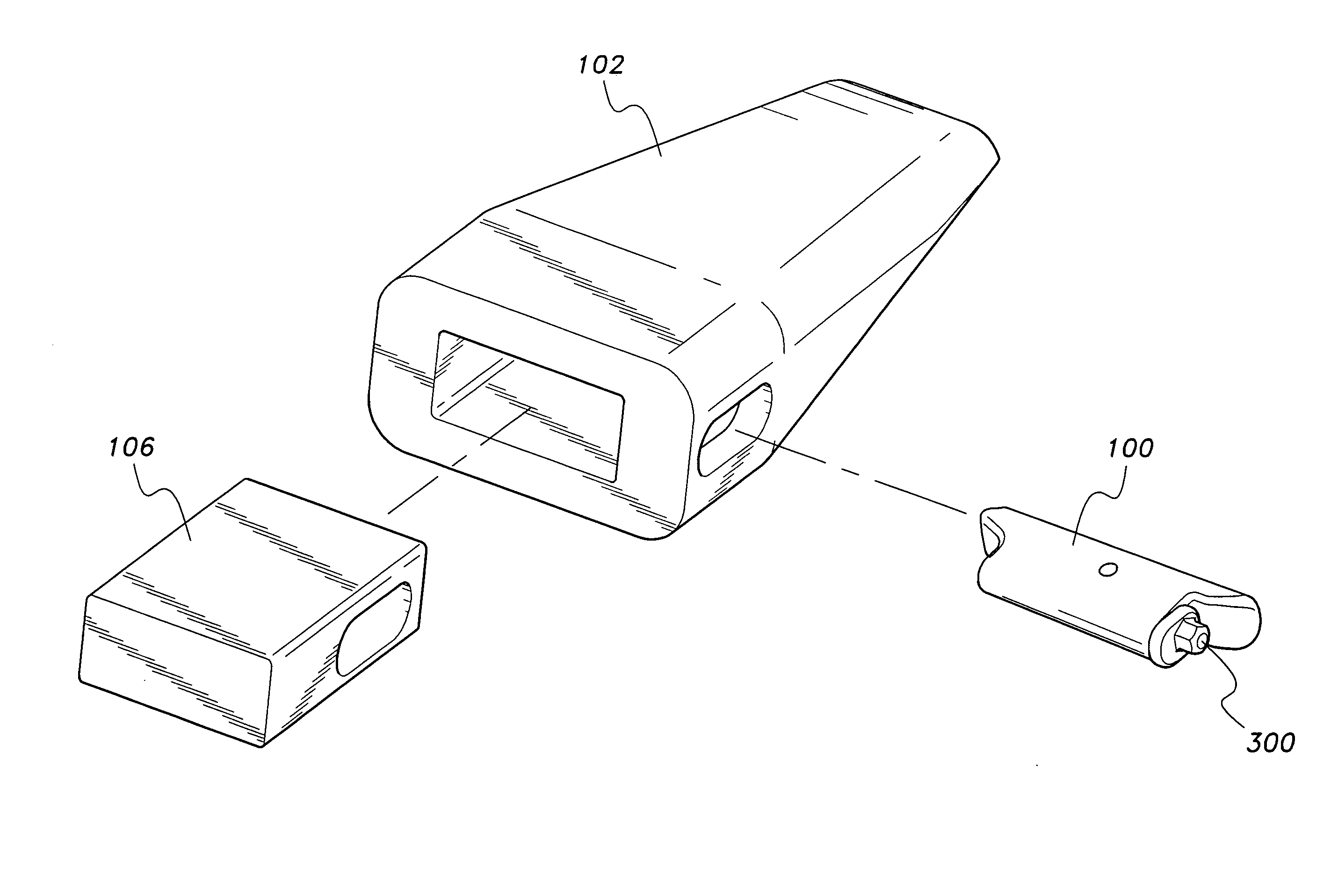
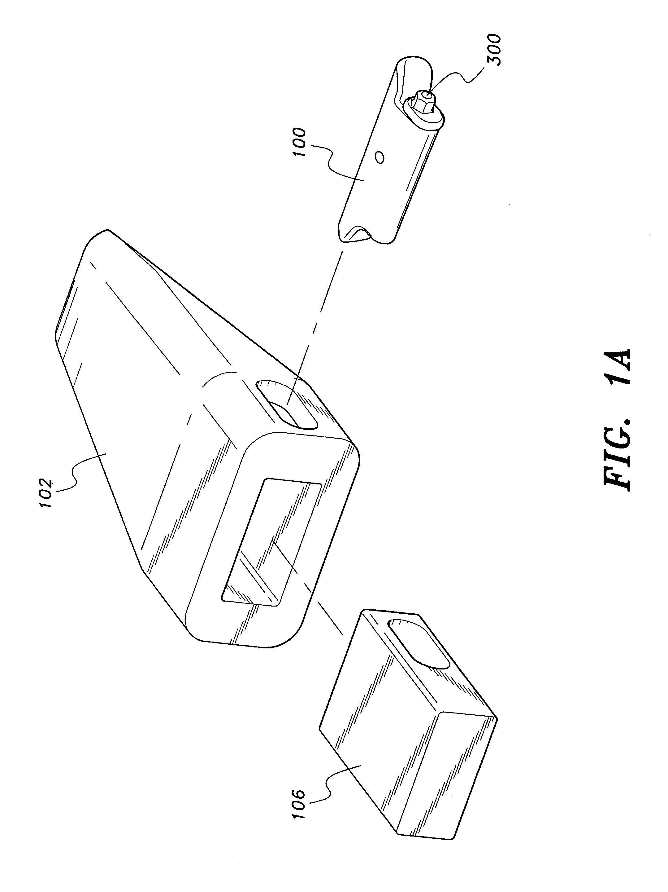
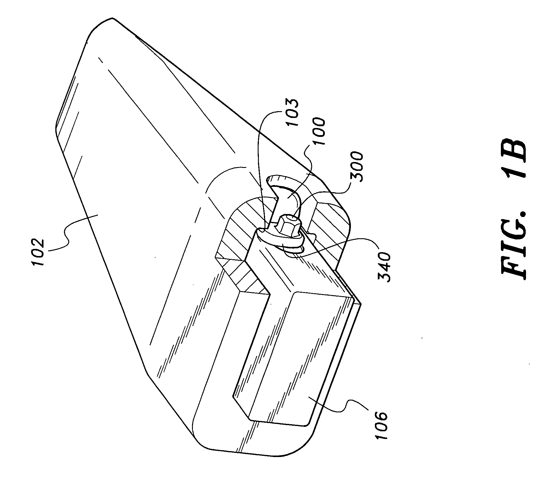
[0021]As shown in FIGS. 1A and 1B, the present invention is a connector pin assembly having a body 100 and a pin 300 designed to releasably retain telescoped excavating support and wear members, such as adapter 106 and tooth 102 in their telescoped relationship. The connector pin assembly is removably received in aligned connector openings in the members. The body portion 100 of the assembly blocks removal of the wear member from the support member, and the lock member portion 300 of the assembly is rotatable relative to the body, toward and away from a locking orientation, to releasably lock the body 100 within the connector openings of adapter 106 and tooth 102. As shown in FIG. 1B, retaining lobe 340 is positioned in a locking position under ledge 103 of the tooth body 102. A reverse 90-degree rotation of the lock member 300 unlocks the connector pin assembly so that it can be removed from the aligned connector openings in the members, adapter 106 and tooth 102.

[0022]As shown in ...


PUM


Abstract

The connector pin assembly releasably retains telescoped excavating support and wear members in their telescoped relationship. The connector pin assembly is removably received in aligned connector openings in the members. A body portion of the assembly blocks removal of the wear member from the support member, and a lock member portion of the assembly is rotatable relative to the body, toward and away from a locking orientation, to releasably lock the body within the connector openings. A resilient sleeve having non-circular interior and exterior surfaces with rounded corners is non-slippably disposed over a rotatable shaft of the lock member in order to slidingly and deformably engage a non-circular shaped interior cavity of the body that rotatably receives shaft and sleeve of the lock member. The sleeve yieldingly resists rotational movement of the lock member away from a locking orientation.

Description

CROSS-REFERENCE TO RELATED APPLICATION[0001]This application claims the benefit of U.S. Provisional Patent Application Ser. No. 60 / 904,369, filed Mar. 2, 2007.BACKGROUND OF THE INVENTION[0002]1. Field of the Invention[0003]The present invention relates to material displacement apparatus such as excavating equipment and, in illustrated embodiments thereof, more particularly relates to a connector pin assembly for releasably coupling a replaceable excavating tooth point or other wear member to an associated adapter nose structure.[0004]2. Description of the Related Art[0005]An excavator is generally the heavy-duty equipment that uses digging teeth or cutters on buckets and shovels for construction or other applications. Teeth or other such cutting engagements are wear parts to be replaced frequently. A tooth is an elongated body terminating in a sharp edge. An adaptor connects the other end of the tooth to the bucket. A lock pin assembly retains the tooth and adapter in a telescopic r...

Claims


Application Information

Patent Timeline
IPC IPC(8): E02F9/28
CPCE02F9/2841
Inventor CUI, KAN
Owner CUI KAN
Why Eureka
Try Eureka