Display Apparatus Driving Method, Display Apparatus Driving Device, Program Therefor, Recording Medium Storing Program, and Display Apparatus

a technology of display apparatus and driving device, which is applied in the direction of electric digital data processing, instruments, computing, etc., can solve the problems of less realistic, less clear, less clear image, and less strikingly bright regions to be displayed, so as to achieve clearer, more realistic, and attractive images

Inactive Publication Date: 2008-09-04
SHARP KK
View PDF7 Cites 14 Cited by
  • Summary
  • Abstract
  • Description
  • Claims
  • Application Information

AI Technical Summary

Benefits of technology

[0006]However, even if an entirely bright display is realized by the foregoing conventional arrangement, a strikingly bright region may not be displayed brightly enough as compared with a CRT (cathode-ray tube). This causes such a problem that an image to be displayed may become less clear, less realistic, and less appealing.
[0007]The present invention has been made in view of the foregoing problems, and it is an object of the present invention to provide a display apparatus driving method, a display apparatus driving device, a program therefor, a recording medium storing the program, and a display apparatus, each of which allows a display screen of the display apparatus to display a clearer, more realistic, and more appealing image.

Problems solved by technology

However, even if an entirely bright display is realized by the foregoing conventional arrangement, a strikingly bright region may not be displayed brightly enough as compared with a CRT (cathode-ray tube).
This causes such a problem that an image to be displayed may become less clear, less realistic, and less appealing.

Method used


Image

  • Display Apparatus Driving Method, Display Apparatus Driving Device, Program Therefor, Recording Medium Storing Program, and Display Apparatus
  • Display Apparatus Driving Method, Display Apparatus Driving Device, Program Therefor, Recording Medium Storing Program, and Display Apparatus
  • Display Apparatus Driving Method, Display Apparatus Driving Device, Program Therefor, Recording Medium Storing Program, and Display Apparatus

Examples


embodiment 1

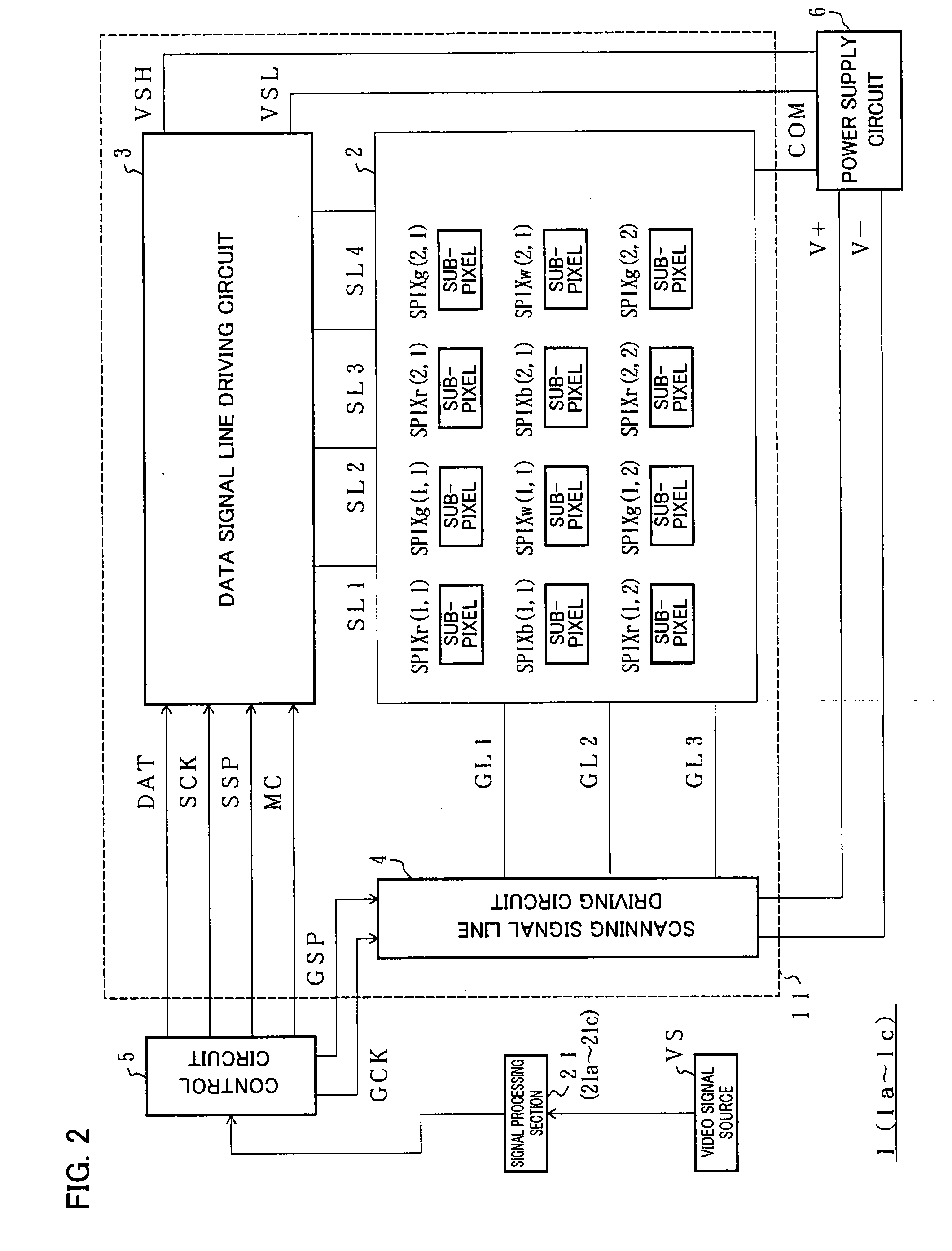
[0054]An embodiment of the present invention will be described below with reference to FIGS. 1 through 7. That is, an image display apparatus 1 according to the present embodiment is an image display apparatus capable of causing a display screen of a display apparatus to display a clearer, more realistic, and more appealing image (sharper image), and can be suitably used, for example, as an image display apparatus of a television receiver or a monitor apparatus of a computer. Note that examples of television broadcasts to be received by the television receiver include: terrestrial television broadcasts; broadcasts, such as BS (Broadcasting Satellite) digital broadcasts and CS (Communication Satellite) digital broadcasts, which uses satellites; and cable television broadcasts.

[0055]The image display apparatus 1 has a pixel which includes sub-pixels capable of displaying R (red), G (green), B (blue), and W (white), respectively, and is a display apparatus that can carry out a color di...

embodiment 2

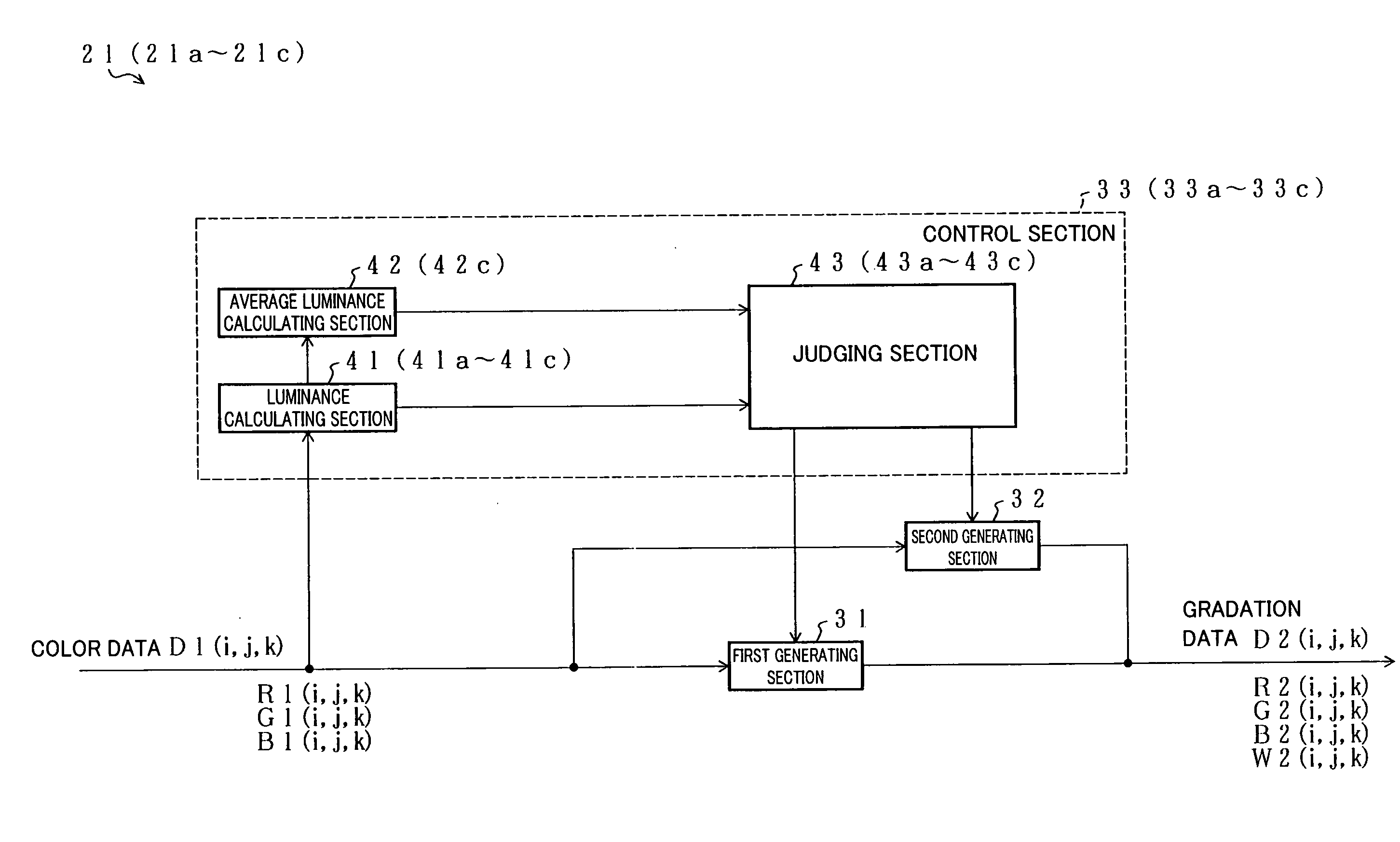
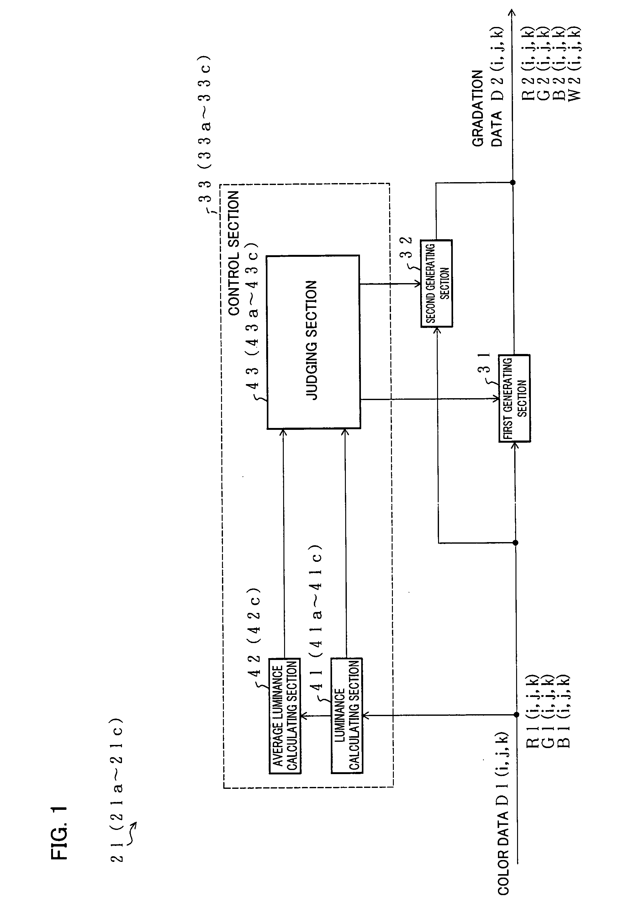
[0109]The present embodiment explains another method for judging the first small region. According to this method, the first region is judged with reference to (i) a standard deviation and (ii) the absolute value of the luminance of a pixel. That is, as shown in FIG. 1, a signal processing section 21a according to the present embodiment is different from Embodiment 1 in terms of a method for judging the first small region, and a judging section 43a is provided instead of the judging section 43.

[0110]The judging section 43 judges, as a high-luminance pixel, a pixel PIX having a luminance that is higher than the average luminance Lave of the display screen by not less than a predetermined level. On the other hand, the judging section 43a judges, as a high-luminance pixel, such a pixel that L(i,j,k)>Lave +α×8 is satisfied (where L(i,j,k) is the luminance of the pixel PIX(i,j), 8 is the standard deviation in luminance of the display screen, and α is a predetermined constant) and that th...

embodiment 3

[0119]Incidentally, in Embodiments 1 and 2, it is judged for each pixel PIX contained in a small region as to whether or not the pixel PIX is a high-luminance pixel, and it is judged, in accordance with the proportion of high-luminance pixels contained in the small region, whether or not the small region is a first small region.

[0120]On the other hand, in the present embodiment, the pixel PIX is replaced by a small block including a plurality of pixels PIX, and it is judged whether or not the small block is a high-luminance block. Then, it is judged, in accordance with the proportion of high-luminance blocks contained in the small region, whether or not the small region is a first small region. The arrangement can be applied to any one of Embodiments 1 and 2. However, the following explains a case where the arrangement is applied to Embodiment 2.

[0121]That is, a signal processing section 21b according to the present embodiment is different from Embodiment 2 in terms of a unit by whi...


PUM


Abstract

A control section is disclosed which divides a display screen into small regions, evaluates the relative brightness of each of the small regions in accordance with color data to be inputted as color data by which each pixel is displayed, and determines whether or not the display screen has a first small region that is brighter than the other small regions by a predetermined degree. Furthermore, the control section causes a first generating device to generate gradation data for use in the first small region, and causes a second generating device to generate gradation data for use in the other small regions. Even if the second generating section receives the same color data as the first generating section does, the second generating section limits the luminance of a W sub-pixel as compared to the first generating section. With this, the first small region can be displayed more strikingly brightly, so that a clearer, more realistic, and more appealing image can be displayed. This makes it possible to realize a display apparatus capable of displaying a clearer, more realistic, and more appealing image.

Description

TECHNICAL FIELD[0001]The present invention relates to a display apparatus driving method, a display apparatus driving device, a program therefor, a recording medium storing the program, and a display apparatus, each of which allows a display screen of the display apparatus to display a clearer, more realistic, and more appealing image.BACKGROUND ART[0002]Liquid crystal display apparatuses that can be driven with a comparatively small amount of power have been widely used not only as image display apparatuses to be provided in stationary apparatuses but also as image display apparatuses to be provided in portable phones. Among these liquid crystal display apparatuses, there is a liquid crystal display apparatus in which a gradation to be displayed by a pixel is controlled by (i) supplying, to a data signal line driving circuit, a digital signal indicating a gradation of each pixel and (ii) causing the data signal line driving circuit to apply, to a data signal line, a voltage corresp...

Claims


Application Information

Patent Timeline
Patent Type & Authority Applications(United States)
IPC IPC(8): G09G5/00
CPCG09G3/3607G09G2320/0613G09G2360/16G09G2340/06G09G2320/0626
Inventor SHIOMI, MAKOTO
Owner SHARP KK
Why Eureka
Try Eureka