
System and method to facilitate manageable and agile deployment of services in accordance with various topologies

a service deployment and topology technology, applied in the field of computer systems, can solve the problems of complex process, increased complexity and cost of process development, application development, testing and deployment within and/or outside an organization, and failure of large deployments that involve multiple components, so as to facilitate the management of services and reduce the extrapolation of topological configurations.

Inactive Publication Date: 2008-09-04
MICROSOFT TECH LICENSING LLC
View PDF14 Cites 31 Cited by
  • Summary
  • Abstract
  • Description
  • Claims
  • Application Information

AI Technical Summary

Benefits of technology

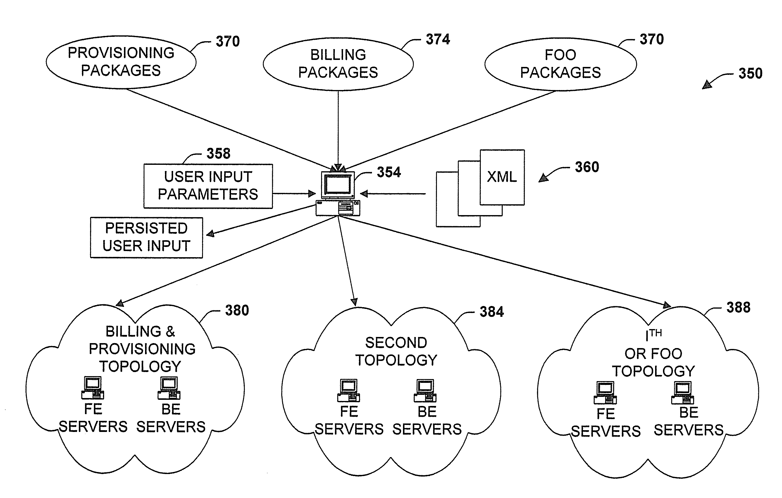
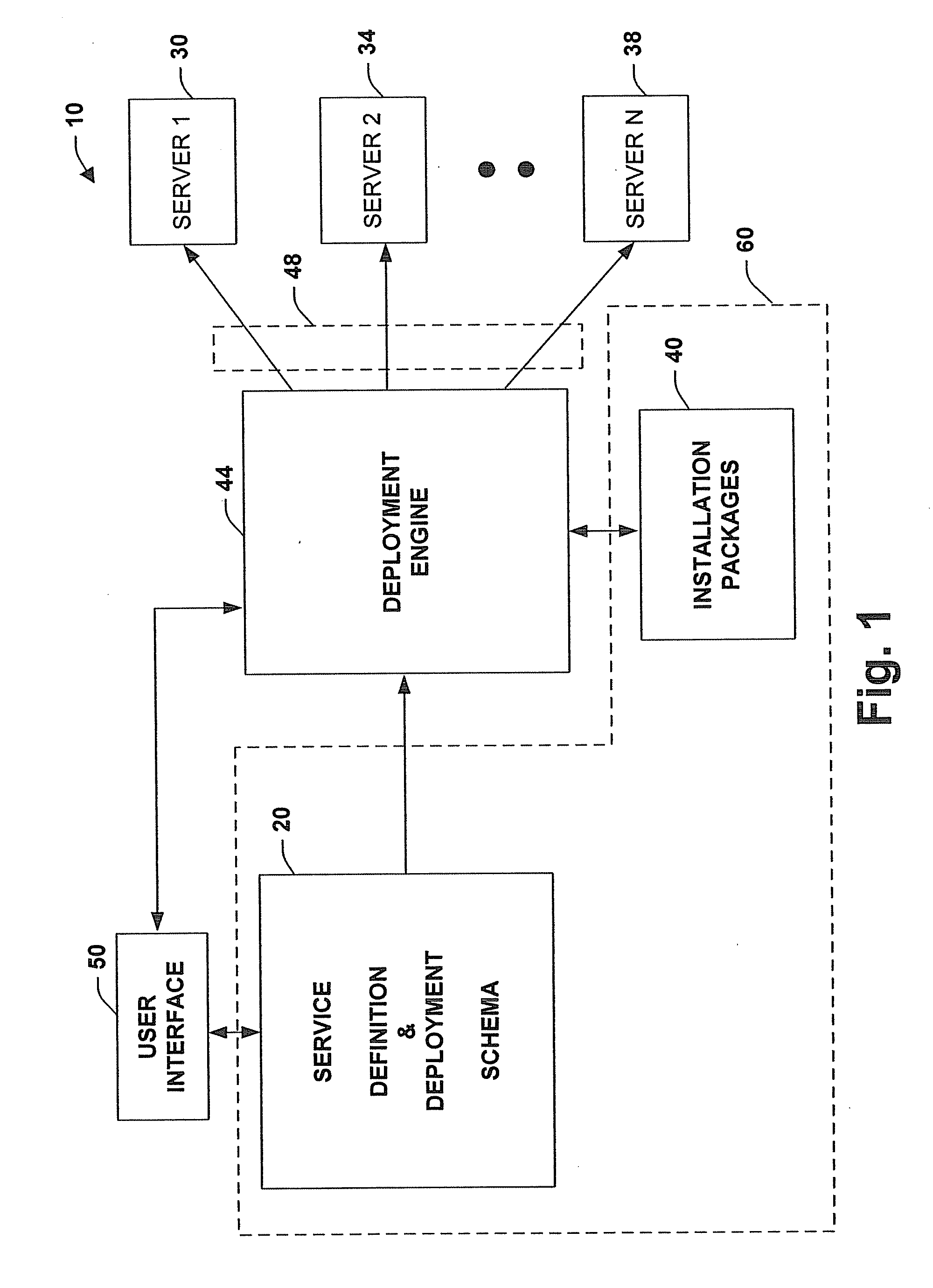
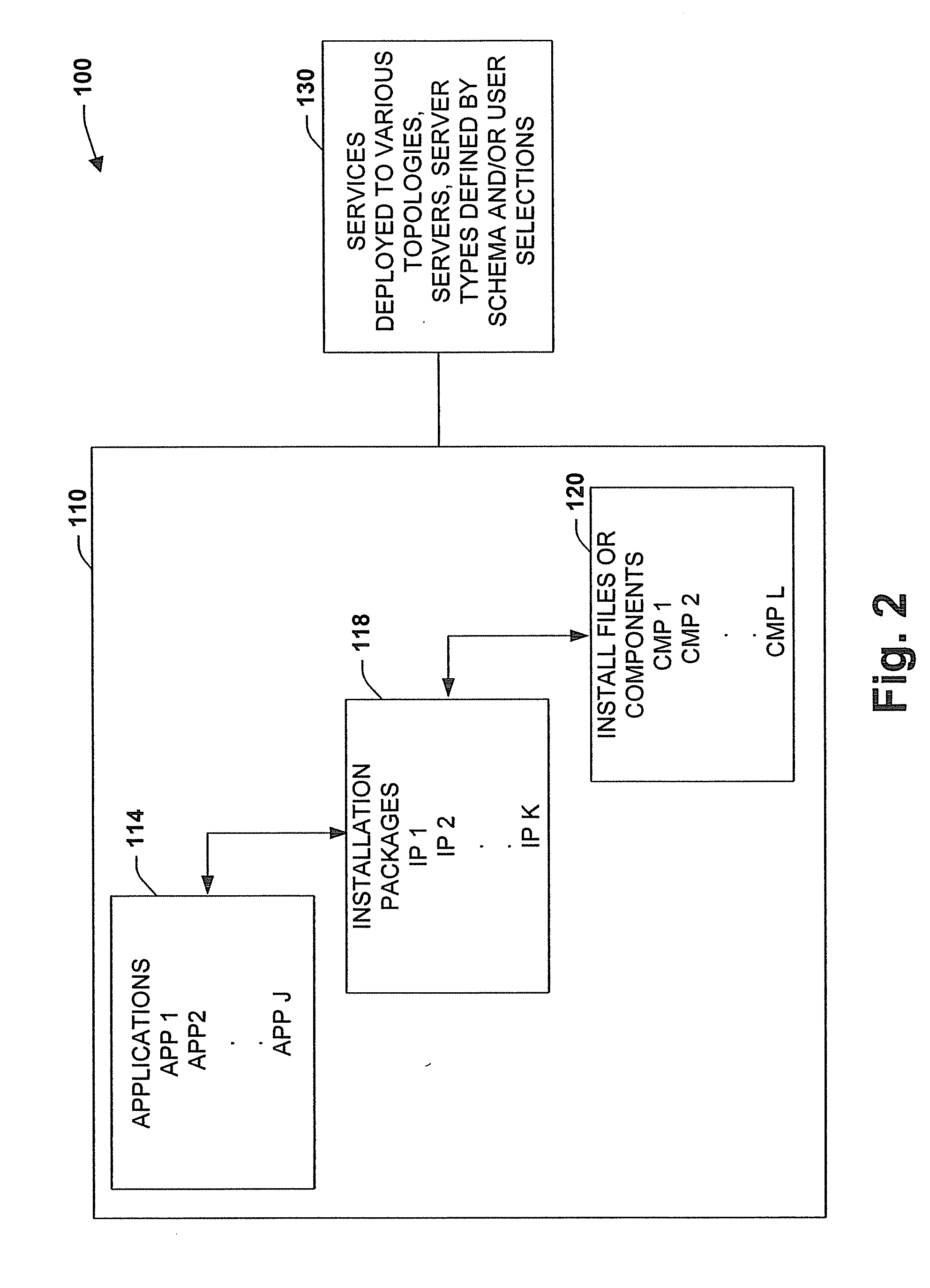
[0008]The present invention relates to a system and methodology providing a framework to facilitate manageable and agile deployment of services in accordance with various and / or different deployment topologies. The framework or architecture includes a schema to describe components of a service and provides an engine to deploy an instance of the service, wherein the components of the service can be distributed across multiple machines and / or machine configurations. The engine utilizes a service description defined in accordance with the schema and in conjunction with topology-specific configuration information to deploy one or more components of the service. Based upon the schema and configuration information, components can be deployed to a plurality of diverse topological configurations associated with service execution. A user interface is also provided to receive deployment-time instructions or configuration information that is operative with the schema to select and implement a plurality of deployment topologies relating to various operational, logistical, and topological requirements of users and / or groups. This enables services to be documented, managed and deployed consistently by different groups or users who participate in various stages of a service life cycle.
[0010]In one aspect of the framework, the schema enables different topologies deployed by developers, testers, operations and / or other groups to be defined in the same document and processed by a single deployment engine, if desired. It is to be appreciated however, that the schema can be associated with a plurality of related schemas or files and the deployment engine can operate in conjunction with or as part of other engines, if desired. The deployment framework mitigates extrapolation of topological configurations employed by previous groups and facilitates that service deployment in a production environment is generally reliable and predictable. The schema provides a defined process for feature or development teams to package services and define deployment attributes of the services. Service property management can also be defined by the schema and implemented by the deployment engine to provide a canonical integration process for the service. In this manner, utilization of a shared process by multiple feature teams in accordance with a canonical integration process by an operations team or other team facilitates manageability of services.

Problems solved by technology

This type of access in many cases has become a complex maze of processes that is often offloaded to third-party systems to manage.
In many situations however, these enterprises now have to grant external access to employees, supply chain partners, contractors and customers.
Moreover, as new applications are developed to meet these challenges, application development, testing and deployment within and / or outside an organization has become increasingly more complicated and expensive.
Thus, the process often fails for a large deployment that involves multiple components, complicated inter-machine coordination, and according to diverse deployment requirements of various teams.
Based upon requirements and complexities associated with larger deployments, many problems can be encountered.
One such problem relates to deployment documents that are substantially static in nature and based on a topology defined by a previous team of developers.
Such extrapolation is generally error-prone and therefore the reliability for future or different deployments suffers.
As a result, deployment in a production environment often fails even though developers and testers claim successful project completion before passing the services to a subsequent team.
Another problem typically encountered relates to various teams utilizing different deployment techniques such as to develop competing script files and packages for service deployment.
This can introduce exponential complexity into service development when an operations staff, for example, manages services developed by multiple feature or development teams.
Therefore, the lack of a consistent integration scheme often introduces redundancy, inconsistency and complexity, thereby increasing the cost of deployment.
Such complexity and inconsistency generally can lead to high operating costs and a low degree of service manageability.

Method used


Image

  • System and method to facilitate manageable and agile deployment of services in accordance with various topologies
  • System and method to facilitate manageable and agile deployment of services in accordance with various topologies
  • System and method to facilitate manageable and agile deployment of services in accordance with various topologies

Examples


example 1

[0036]

value=“1”>value=“0”>

[0037]Referring to FIG. 4, a system 200 illustrates a user interface 210 and deployment selections in accordance with an aspect of the present invention. The user interface 210 generally includes an associated display 214 to provide feedback and output data to a user regarding various aspects of service deployment. The display 214 can include display objects (e.g., icons, buttons, sliders, input boxes, selection options, menus, tabs and so forth) having multiple dimensions, shapes, colors, text, data and sounds to facilitate service deployment. In addition, various menus and alternative screens or display outputs can be provided that perform a plurality of aspects of the present invention and will be described in more detail below. The user interface 210 can also be associated with a plurality of inputs 218 for adjusting and configuring one or more aspects of the present invention. This can include receiving user commands from a mouse, keyboard, speech inpu...

example 2

[0046]

ServiceDeployment.xmlServiceDefinition.xmlapplication=“resourcemgr” / >prompt=“Service Account Name”helpString=“Enter the user name of the account to use to run the Hostingservices.”default=“HstServiceAcct” / >prompt=“Service Account Password”helpString=“Enter the password of the account to use to run the Hostingservices.”default=“”type=“string” / >key=“ServiceAccountName” / >key=“ServiceAccountPassword” / >prompt=“Provisioning Log File”helpString=“Enter the path to use for the Provisioning Log file”default=“[%systemdrive]:\kws\auditdb”type=“string” / >key=“ServiceAccountName” / >key=“ServiceAccountPassword” / >

[0047]FIG. 8 is a diagram illustrating an opening page, menu and / or sequence user interface 400 to select and deploy services according to a desired topology in accordance with an aspect of the present invention. The interface 400 enables selection of a location of installation packages or files at 410 that can include a browse option for locating files at 412. This can also include...


PUM


Abstract

The present invention relates to a system and methodology to facilitate service deployment in a distributed computing and applications environment. A schema is provided that describes various components of a service and various topologies for execution of the services, wherein a deployment engine utilizes the schema in conjunction with user inputs to determine one or more destination locations for the service. The topologies relate to various machine and / or machine types defined for various groups or individuals that employ the service. A user interface can be provided to receive user inputs for topological selections and to facilitate various parametric configurations associated with service deployment and subsequent execution thereof.

Description

CROSS-REFERENCE TO RELATED APPLICATIONS[0001]This application is a divisional of U.S. patent application Ser. No. 10 / 113,610, filed Apr. 1, 2002, entitled “SYSTEM AND METHOD TO FACILITATE MANAGEABLE AND AGILE DEPLOYMENT OF SERVICES IN ACCORDANCE WITH VARIOUS TOPOLOGIES”. The entirety of the aforementioned application is incorporated herein by reference.TECHNICAL FIELD[0002]The present invention relates generally to computer systems, and more particularly to a system and method to manage deployment of services according to diverse group or user requirements and in accordance with a plurality of system topologies relating thereto.BACKGROUND OF THE INVENTION[0003]Network technologies such as the Internet have provided users and other entities with virtually unlimited access to remote systems and associated applications. This type of access in many cases has become a complex maze of processes that is often offloaded to third-party systems to manage. Application heterogeneity has increas...

Claims


Application Information

Patent Timeline
Patent Type & Authority Applications(United States)
IPC IPC(8): G06F3/048
CPCG06Q30/04
Inventor JORDAN, KENNETH EUGENELAN, ERICA SUI-CHING
Owner MICROSOFT TECH LICENSING LLC
Learn More