Joint for connecting two tubes in a high-temperature environment

a technology for connecting two tubes and high-temperature environments, which is applied in the direction of fluid pressure sealed joints, pipes/joints/fittings, adjustable joints, etc., can solve the problems of deteriorating the quality of connection, inability to resist high temperature, and inability to perfect ball-cup connections. to achieve the effect of preventing ingress and egress

Active Publication Date: 2008-09-11
ASM INTERNATIONAL
View PDF9 Cites 0 Cited by
  • Summary
  • Abstract
  • Description
  • Claims
  • Application Information

AI Technical Summary

Benefits of technology

[0007]Another object of the present invention is to provide a ball-cup connection that prevents the ingress and egress of gases in a high-temperature environment.
[0008]Another object of the present invention is to provide a ball-cup connection that prevents the ingress and egress of gases under sub-atmospheric or super-atmospheric pressure conditions.

Problems solved by technology

Since the diffusion of gases occurs over the line contact easily, the ball-cup connection is not perfect.
However, at very high temperatures, the O-ring may degenerate and deteriorate the quality of the connection.
However, due to the use of the O-ring, the ultratorr connection is not resistant to high temperatures.

Method used


Image

  • Joint for connecting two tubes in a high-temperature environment
  • Joint for connecting two tubes in a high-temperature environment
  • Joint for connecting two tubes in a high-temperature environment

Examples


Embodiment Construction

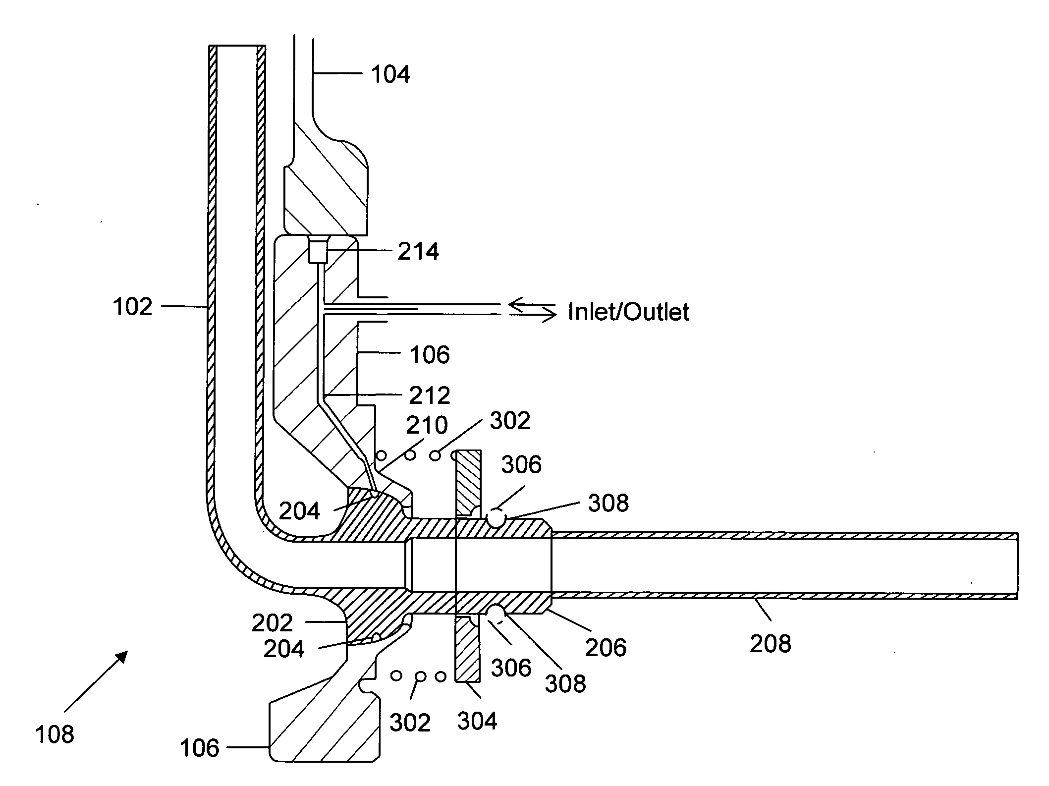
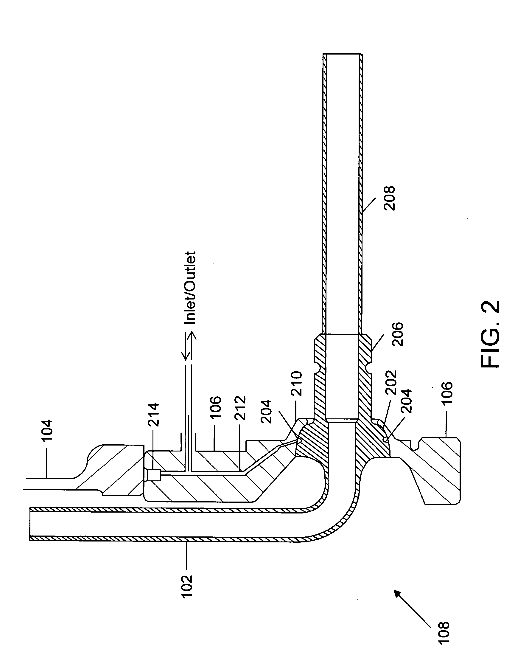
[0015]The present invention provides a ball-cup connection for connecting two tubes in a high-temperature environment. The ball-cup connection prevents the ingress and egress of gases.

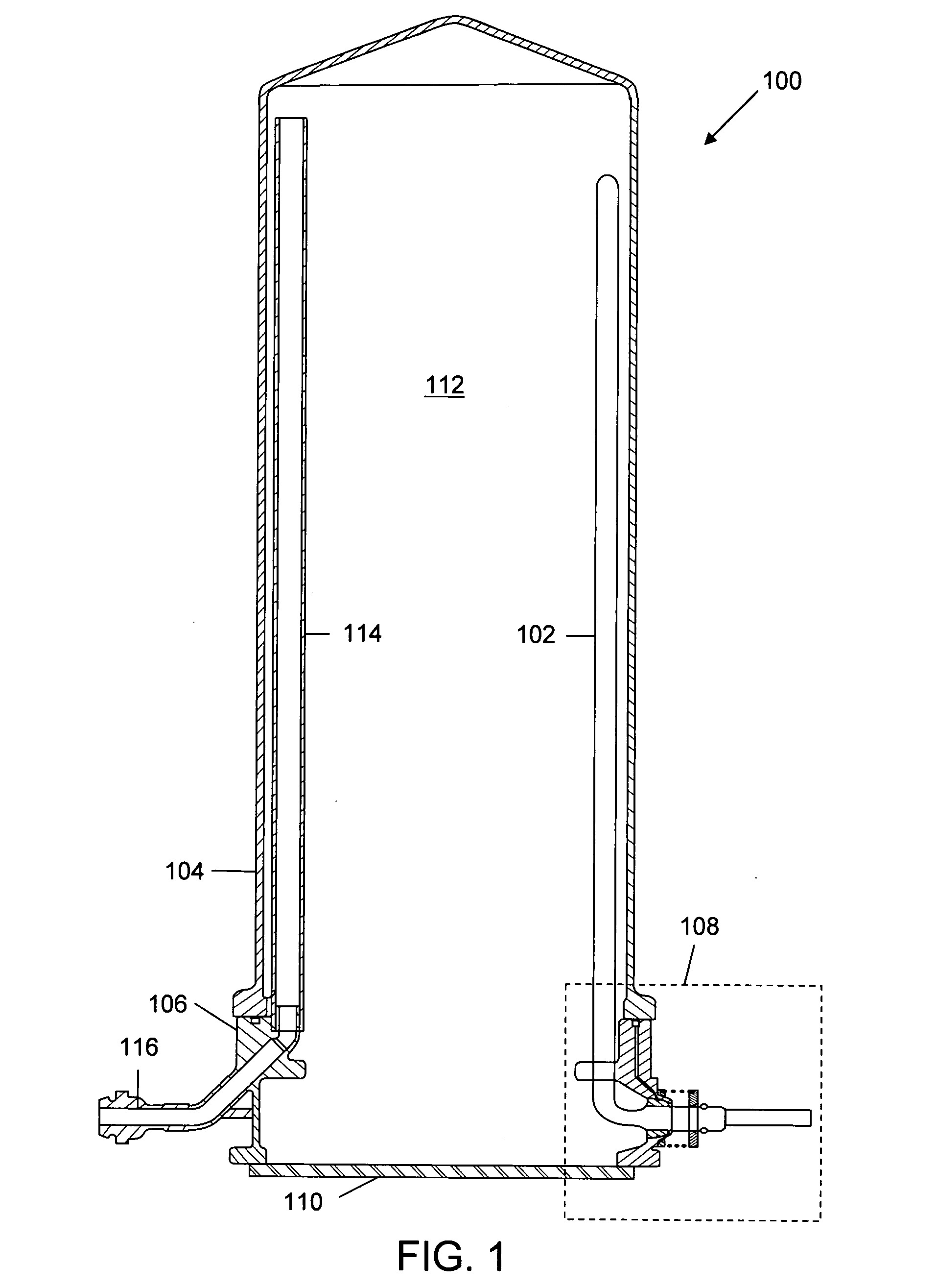
[0016]FIG. 1 is a diagram illustrating an exemplary furnace 100 in which the present invention may be practiced. Furnace 100 includes a first tube 102, a second tube comprising a process tube 104 and a support tube 106, a ball-cup connection 108, a closure 110, a reaction chamber 112, a gas-dispersion tube 114, and a gas-feed tube 116. The second tube and closure 110 delimit process chamber 112. Furnace 100 is heated by a heater, not shown in the figure, which is provided around the second tube.

[0017]A substrate may be processed at elevated temperatures in furnace 100 by passing process gases through the second tube. The substrate is placed inside the second tube through a closeable opening at the bottom end of the second tube. In the closed state, the closeable opening is closed by closure 110. A subs...


PUM


Abstract

A joint for connecting two tubes. The joint includes a first tube that provides a ball interface at its end. The joint also includes a second tube that provides a cup interface inside its wall. The cup interface of the second tube and the ball interface of the first tube form a cup-ball interface. This cup-ball interface is located in the interior of the second tube.

Description

BACKGROUND OF THE INVENTION[0001]The present invention generally relates to the field of joints for connecting two tubes. More specifically, the present invention relates to connecting two tubes through a ball-cup connection in a high temperature environment.[0002]In high temperature furnaces, tubes made of ceramic materials need to be connected to each other. These tubes may be process tubes, gas-feed tubes, gas-exhaust tubes, thermocouple tubes, and the like. The connection between two tubes is designed such that ingress and egress of gases is prevented.[0003]Ball-cup connections are generally used to prevent ingress and egress of gases. In such a connection, a ball provided on a tube and a mating cup provided on another tube form in a mating and contacting position, wherein the surface-to-surface contact provides a mechanical seal. Typically, a ball and cup are made of the same material, and the design is such that the tolerances in the sizing of the ball and the cup can be accom...

Claims


Application Information

Patent Timeline
Patent Type & Authority Applications(United States)
IPC IPC(8): F16L17/00
CPCF16L25/0072F16L49/08F16L27/06
Inventor DE RIDDER, CHRISTIANUS GERARDUS MARIA
Owner ASM INTERNATIONAL
Why Eureka
Try Eureka