Mixing device

Active Publication Date: 2008-09-11
REVALESIO CORP
View PDF6 Cites 64 Cited by
  • Summary
  • Abstract
  • Description
  • Claims
  • Application Information

AI Technical Summary

Problems solved by technology

The non-axial and orthogonal flow, and the presence of the host material in the gap between the first end of the rotor 12 and the housing 34 causes undesirable and unnecessary friction.
Further, it is possible for a portion of the host material to become trapped in eddy currents swirling between the first end of the rotor and the housing.
As mentioned above, the non-axi

Method used


Image

  • Mixing device
  • Mixing device
  • Mixing device

Examples


Embodiment Construction

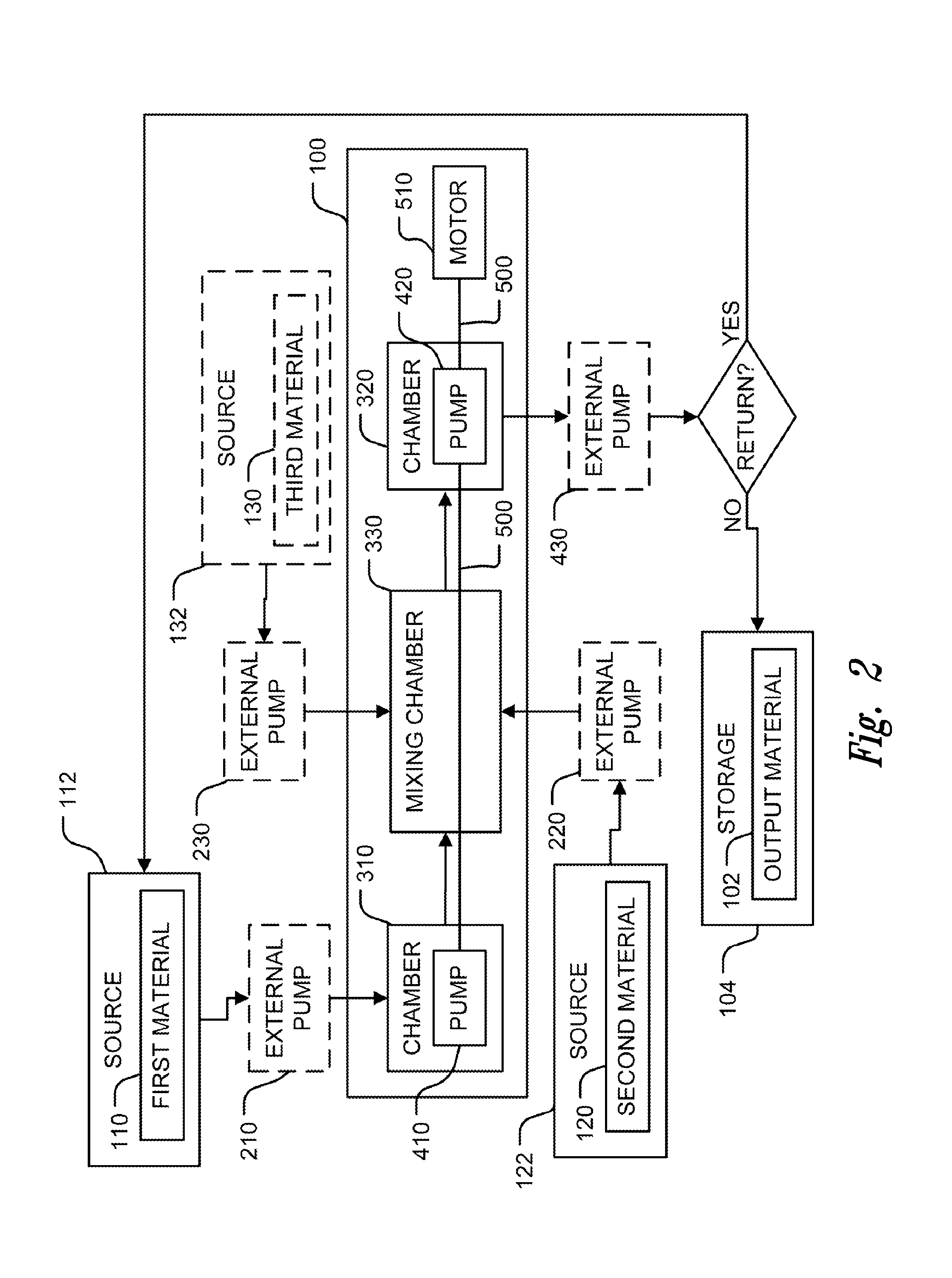
[0057]FIG. 2 provides a block diagram illustrating some of the components of a mixing device 100 and the flow of material into, within, and out of the device. The mixing device 100 combines two or more input materials to form an output material 102, which may be received therefrom into a storage vessel 104. The mixing device 100 agitates the two or more input materials in a novel manner to produce an output material 102 having novel characteristics. The output material 102 may include not only a suspension of at least one of the input materials in at least one of the other input materials (e.g., emulsions) but also a novel combination (e.g., electrostatic combinations) of the input materials, a chemical compound resulting from chemical reactions between the input materials, combinations having novel electrostatic characteristics, and combinations thereof.

[0058]The input materials may include a first material 110 provided by a source 112 of the first material, a second material 120 p...


PUM

PropertyMeasurementUnit
Thicknessaaaaaaaaaa
Thicknessaaaaaaaaaa
Poweraaaaaaaaaa

Abstract

A mixing device for mixing a first and second material together to create an output mixture. The device includes a first chamber containing the first material coupled to a mixing chamber defined between a rotor and a stator. The rotor is disposed inside the stator and rotates therein about an axis of rotation. The first chamber houses an internal pump configured to pump the first material from the first chamber into the mixing chamber. The pump may be configured to impart a circumferential velocity into the first material before it enters the mixing chamber. At least one of the rotor and stator have a plurality of through-holes through which the second material is provided to the mixing chamber. Optionally, a second chamber is coupled to the mixing chamber. The second chamber may house an internal pump configured to pump the output material from the mixing chamber into the second chamber.

Description

CROSS REFERENCE TO RELATED APPLICATION(S)[0001]This application claims the benefit of U.S. Provisional Application Nos. 60 / 862,904, filed Oct. 25, 2006, 60 / 862,955, filed Oct. 25, 2006, and 60 / 982,38, filed Oct. 24, 2007.BACKGROUND OF THE INVENTION[0002]1. Field of the Invention[0003]The present invention is directed generally to mixing devices and more particularly to mixing devices that mix two or more materials between surfaces, including such as between a rotating rotor and a stationary stator.[0004]2. Description of the Related Art[0005]FIG. 1 provides a partial block diagram, partial cross-sectional view of a prior art device 10 for diffusing or emulsifying one or two gaseous or liquid materials (“infusion materials”) into another gaseous or liquid material (“host material”) reproduced from U.S. Pat. No. 6,386,751, incorporated herein by reference in its entirety. The device 10 includes a housing configured to house a stator 30 and a rotor 12. The stator 30 encompasses the rot...

Claims


Application Information

Patent Timeline
IPC IPC(8): B01F7/00B01F3/00B01F23/00B01F27/74B01F23/10
CPCB01F3/04531B01F3/0807B01F3/0853B01F7/00816A61K33/00B01F7/008A61J3/00A61K9/10C09K3/00A23L2/54C02F1/727C02F3/02A61K9/08C12M27/00A61P17/02A61P27/02Y02W10/10B01F23/233B01F23/43B01F23/41B01F27/2722B01F25/4413B01F23/23B01F27/272
Inventor WOOD, ANTHONY B.ARCHAMBEAU, GREGORY J.WATSON, RICHARD L.
Owner REVALESIO CORP
Why Eureka
Try Eureka