
Pen with bent tip

a writing pen and tip technology, applied in the direction of nibs, brushes, printing, etc., can solve the problems of no practical value of cited references, user's inability to grasp the lowest portion of the writing pen with the fingers, and the writing pen cannot provide users with good efficiency as a bent writing pen. achieve the effect of stable and comfortable postur

Inactive Publication Date: 2008-09-11
LEE SUN JOO +1
View PDF6 Cites 6 Cited by
  • Summary
  • Abstract
  • Description
  • Claims
  • Application Information

AI Technical Summary

Benefits of technology

[0020]Accordingly, the present invention has been made in an effort to solve the above-mentioned problems occurring in the prior arts, and it is an object of the present invention to provide a writing pen with a rotation-preventing bent tip, which has a structure allowing a user to write down in the most stable and comfortable posture.
[0021]It is another object of the present invention to provide a writing pen with a rotation-preventing bent tip, which can effectively prevent vertebral troubles and a shoulder-inclination-symptom frequently caused to students, literary writers and pen character artists who seat and write down for a long time, and gradually correct such troubles and symptom while the user uses it.
[0022]It is a further object of the present invention to provide a writing pen with a bent rotation-preventing tip, which can be easily manufactured through a simple manufacturing process.
[0023]To accomplish the above object, according to the present invention, there is provided a writing pen with a rotation-preventing bent tip, which has a bent portion formed at a central portion of the tip coupled to an end of a tip housing and a rotation-preventing protrusion formed at an end thereof, the bending angle being 50°±5°, whereby a user can write down in the most stable and comfortable posture.

Problems solved by technology

However, the writing pen cannot provide users with good efficiency as a bent writing pen.
So, the cited reference has no practical value, and is unmarketable.
However, considering that the lower end portion of the outer casing, namely, a hand-grip of the writing pen, is bent, since the lowest location of the writing pen, namely, a narrow tube portion where the outer casing starts to become narrow, cannot be bent, a portion above the narrow tube portion of the writing pen is inevitably bent, and so, the user cannot grasp the lowest portion of the writing pen with the fingers but has to grasp the portion located at a predetermined height.
Therefore, when the user uses the writing pen according to the cited reference, since the user cannot write down in a stable posture that the hand grasping the writing pen is in contact with the paper surface, the user's hand is shaken, and so, the user cannot obtain a good style of penmanship.
When the user writes down for a long time in the above state, the user may feel a great fatigue since the user sets his or her nerves on writing and consumes energy.
In addition, if the above state is continued, many students who are in a growth period and many office workers who have to use the writing pens for a long time vocationally suffer from a phenomenon of bent vertebrae.
Furthermore, the cited reference does not consider manufacturing process and method.
The writing pen according to the cited reference cannot be made with a double-sided slide mold of a relatively good efficiency, and is difficult to be injection-molded.
So, even though the writing pens of the above structure can be manufactured and supplied to consumers, since they cannot be supplied to the consumers in an inexpensive price which the consumers want, the cited reference is an invention which has no practical value in fact.

Method used


Image

  • Pen with bent tip
  • Pen with bent tip
  • Pen with bent tip

Examples


Embodiment Construction

[0047]Reference will be now made in detail to the preferred embodiment of the present invention with reference to the attached drawings. The same parts have the same reference numerals in drawings.

[0048]A first preferred embodiment of the present invention will be described.

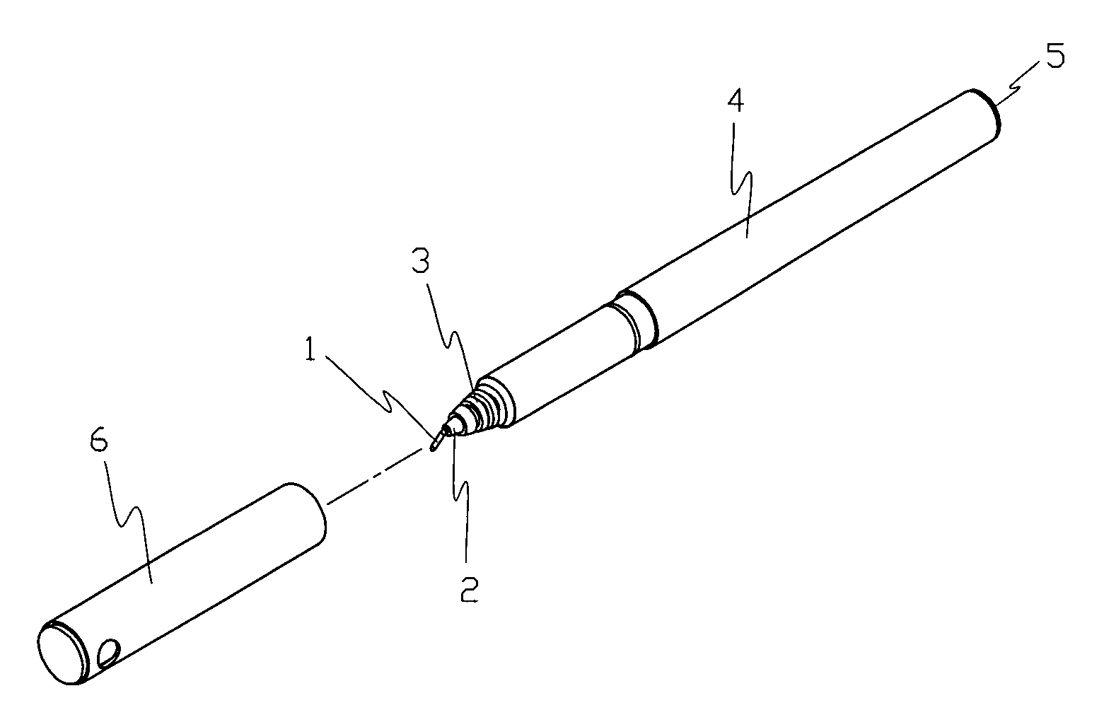
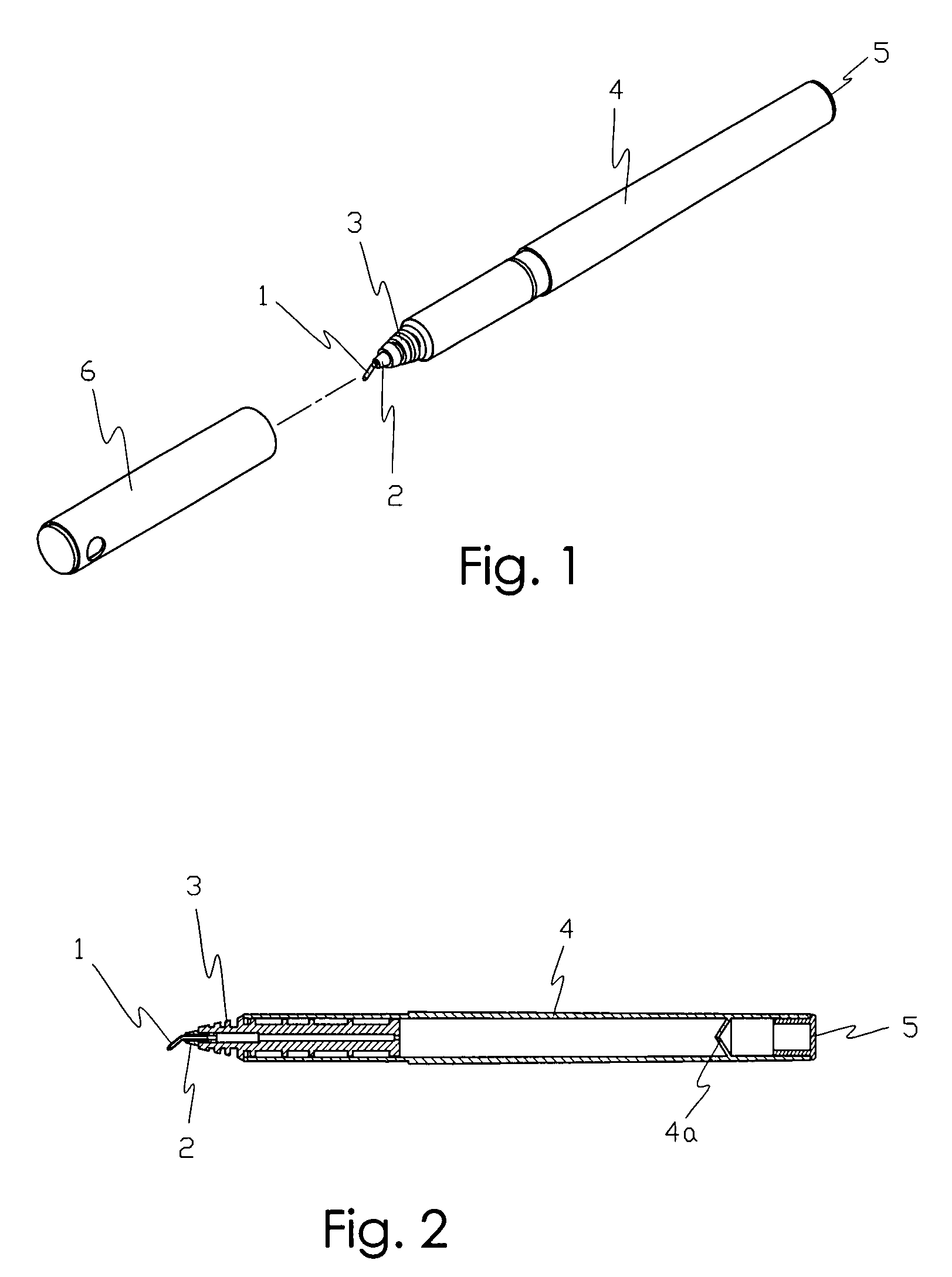
[0049]According to the first preferred embodiment illustrated in FIG. 1, a tip 1 is made of tungsten, stainless steel or the like metallic material. The tip 1 is manufactured by a bending method, a cold expansion method or others, and fittingly coupled to a tip housing 2.

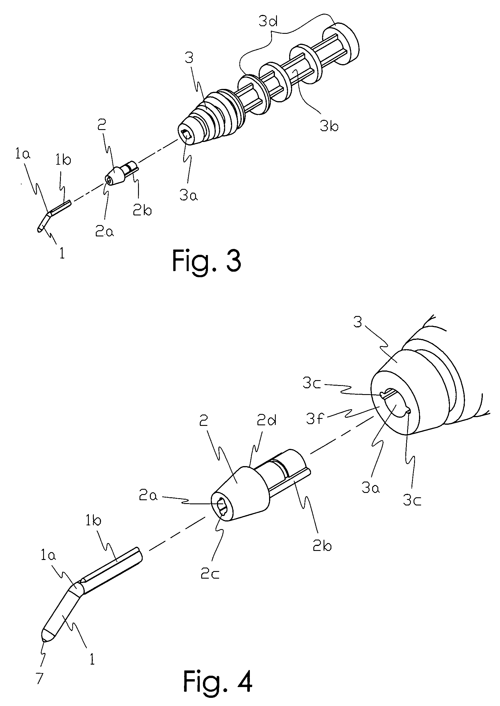
[0050]In this instance, the tip 1 includes: a bent portion la having an end, to which a ball is inserted, and bent at its central portion at an angle of 50°±5°; and a rotation-preventing protrusion 1b protrudingly formed on the outer peripheral surface of a straight tubular body thereof in a longitudinal direction.

[0051]The tip housing 2, to which the other end of the tip 1 is coupled, is made of synthetic resin and injection-molded. The tip hous...


PUM


Abstract

Disclosed therein is a writing pen with a rotation-preventing bent tip. The writing pen includes a rotation-preventing bent tip and a tip housing which are coupled to each other in a key-locking type to prevent a rotation of the tip or the tip housing by a pressing force generated when a user writes down. The tip 1 has a rotation-preventing protrusion 1b, the tip housing 2 has a rotation-preventing protrusion 2b and a groove 2c to which the protrusion 1b is coupled, and a main housing 3 has a groove 3c to which the protrusion 2b is coupled, so that the tip 1, the tip housing 2 and the main housing 3 are coupled to one another in the key-locking type to thereby provide a mutual interrupting action. So, even though a great force is applied to the writing pen when a user writes down, the tip 1 is not rotated, so that the user can use it freely and comfortably without regard to a used angle of the writing pen.

Description

BACKGROUND OF THE INVENTION[0001]1. Field of the Invention[0002]The present invention relates to a writing pen with a bent tip which has a plurality of components, and more particularly, to a writing pen with a bent tip prevented in rotation.[0003]2. Background Art[0004]Korean Utility Model Publication No. 20-174278 discloses a writing pen, which has a front end part bent at a proper angle according to a user's grasping angle, and whose a front end of a refill combined inside an outer casing is worn in balance. In Korean Utility Model Publication No. 20-174278, the writing pen, in which the refill having a cylindrical tube for charging ink therein and a metallic ball bearing mounted on the front end thereof is combined inside the tubular outer casing, or, which has a pen point for writing, includes a grasping part formed on the front end of the outer casing of the writing pen and bent to keep a predetermined angle in one direction or the pen point inwardly bent at a predetermined an...

Claims


Application Information

Patent Timeline
Patent Type & Authority Applications(United States)
IPC IPC(8): A46B5/02B43K7/10
CPCB43K1/00B43K7/10B43K7/00B43K1/08B43K3/00
Inventor LEE, SUN JOOHAM, CHUN SIK
Owner LEE SUN JOO
Learn More