Conveyor with accumulating slip rolls

a conveyor and slip roll technology, applied in the direction of conveyor parts, roller-ways, transportation and packaging, etc., can solve the problem that the conventional conveyor cannot transition directly to a slow speed without, and achieve the effect of reducing or eliminating wasted conveyor space, reducing skid damage, and saving costs

a conveyor and slip roll technology, applied in the direction of conveyor parts, roller-ways, transportation and packaging, etc., can solve the problem that the conventional conveyor cannot transition directly to a slow speed without, and achieve the effect of reducing or eliminating wasted conveyor space, reducing skid damage, and saving costs

US20080236998A1Inactive Publication Date: 2008-10-02DURR SYST INC

Image

  • Conveyor with accumulating slip rolls
  • Conveyor with accumulating slip rolls
  • Conveyor with accumulating slip rolls

Examples


Embodiment Construction

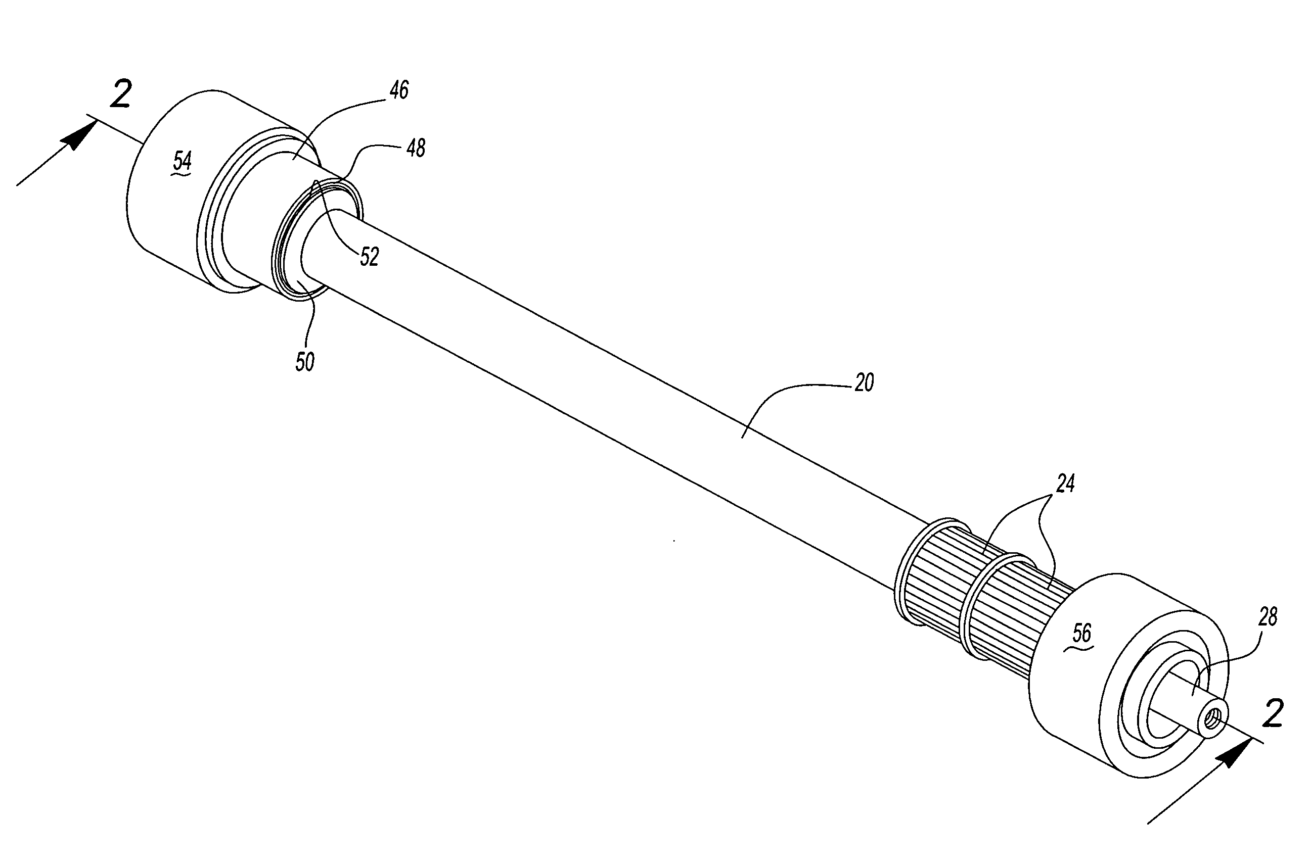
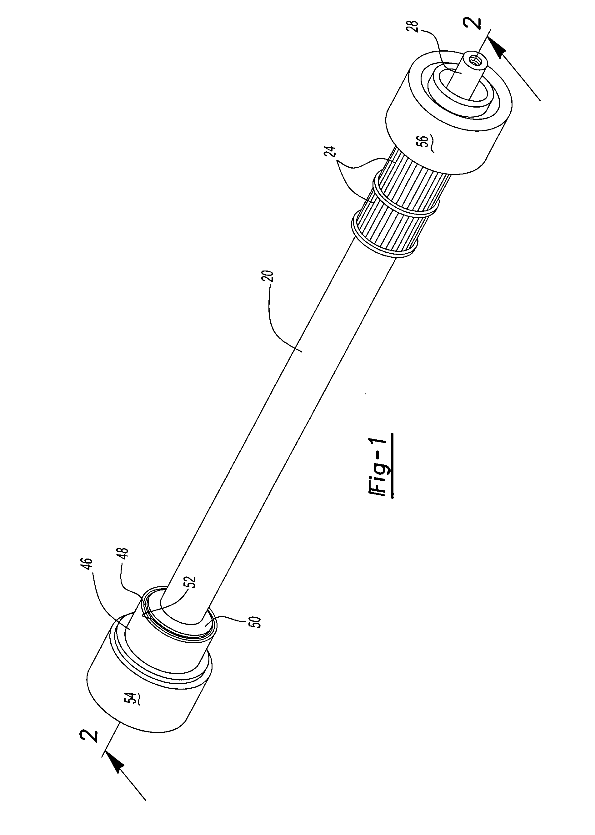
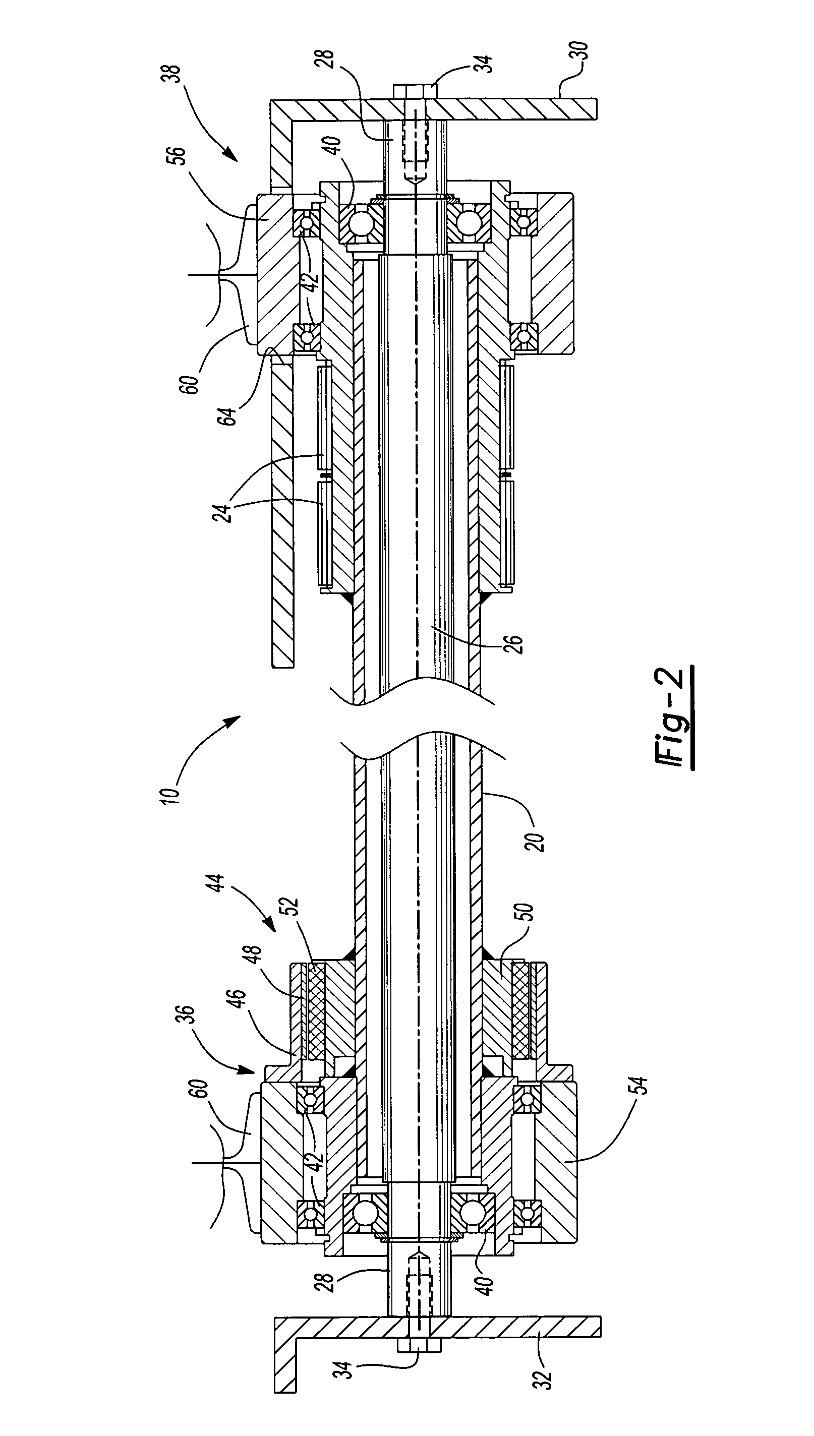
[0010]The embodiment of the magnetic accumulating slip roller assembly 10 shown in FIGS. 1 and 2 includes a drive axle 20 which, in the disclosed embodiment, is tubular as shown in FIG. 2. The drive axle 20 in the disclosed embodiment is driven by a motor 22 shown in FIG. 3 and described below. In this embodiment, the drive axle includes splined pulleys 24 which receive splined drive belts 58 as shown in FIG. 3 and described below. As will be understood by those skilled in this art, the pulleys 24 may be replaced with sprockets (not shown) and the accumulating slip roller assembly will then be driven by drive chains.

[0011]In the disclosed embodiment, the accumulating slip roller assembly 10 further includes a fixed inner axle 26 which is fixed to and supported on the frame assembly members 30 and 32 as shown in FIG. 2. In the disclosed embodiment, the fixed inner axle 26 includes end portions 28 which are retained to the frame members 30 and 32 by screws 34.

[0012]The accumulating sl...


PUM


Abstract

A magnetic accumulating slip roller assembly of a conveyor including a drive axle rotatably driven by a motor, spaced rollers for receiving a skid or other element to be conveyed by the conveyor system supported on the drive axle including a drive roller and an idler roller and a magnetic clutch between the drive roller and the drive axle allowing the drive roller to rotatably slip as the drive axle is rotated by the motor. In the disclosed embodiment, the drive axle is tubular and rotatably supported on a fixed inner axle.

Description

RELATED APPLICATION[0001]This application claims priority to U.S. Provisional Patent Application Ser. No. 60 / 921,056 filed Mar. 30, 2007.FIELD OF THE INVENTION[0002]This invention relates to magnetic accumulating slip rolls of conveyor systems particularly, but not exclusively, for transporting heavy objects, such as used by the automotive industry for conveying skids having automotive bodies and other components.BACKGROUND OF THE INVENTION[0003]Conveyor systems of the type disclosed herein include suspension rollers, including a drive roller and a driven or idler roller which rotatably receive the conveyor skids. In a typical application, the shaft of the roller assembly includes chain sprockets or a belt pulley which receive a chain or belt connected to a motor / motor reducer. The skids, including the conveyed objects, are received on the suspension rollers and are driven by the drive roller and motor. A roller bed of a conventional conveyor is about 20 feet in length and includes ...

Claims


Application Information

Patent Timeline
02 Oct 2008
Publication
US20080236998A1
IPC
B65G13/00
CPC
B65G13/071; B65G47/261
Inventors
SHURKO, ROBERT EDWARD