Pin and grommet fastener assembly

a technology of fasteners and components, applied in the direction of threaded fasteners, snap fasteners, screw fasteners, etc., can solve the problems of adding labor time and costs, requiring separate tooling, and forming separate adjustable features

Inactive Publication Date: 2008-10-23
ILLINOIS TOOL WORKS INC
View PDF3 Cites 47 Cited by
  • Summary
  • Abstract
  • Description
  • Claims
  • Application Information

AI Technical Summary

Benefits of technology

[0012]The opposing flexible wings may flex toward one another when the grommet is snapably secured into the hole of the second panel. The opposing flexible wings prevent the walls that define the central passage from outwardly bowing (thereby expanding the central passage in one direction) when the grommet is snapably secured into the hole of the second panel.
[0013]The grommet may also include locating protuberances that are configured to locate and align the grommet with respect to the hole of the second panel. The locating protuberances may also provide barriers that prevent the opposing flexible wings from over-flexing when the grommet is secured in the hole.

Problems solved by technology

Separate tooling and additional labor is typically needed to form the adjustable feature.
Consequently, forming the separate adjustable features add labor time and costs.

Method used


Image

  • Pin and grommet fastener assembly
  • Pin and grommet fastener assembly
  • Pin and grommet fastener assembly

Examples


Embodiment Construction

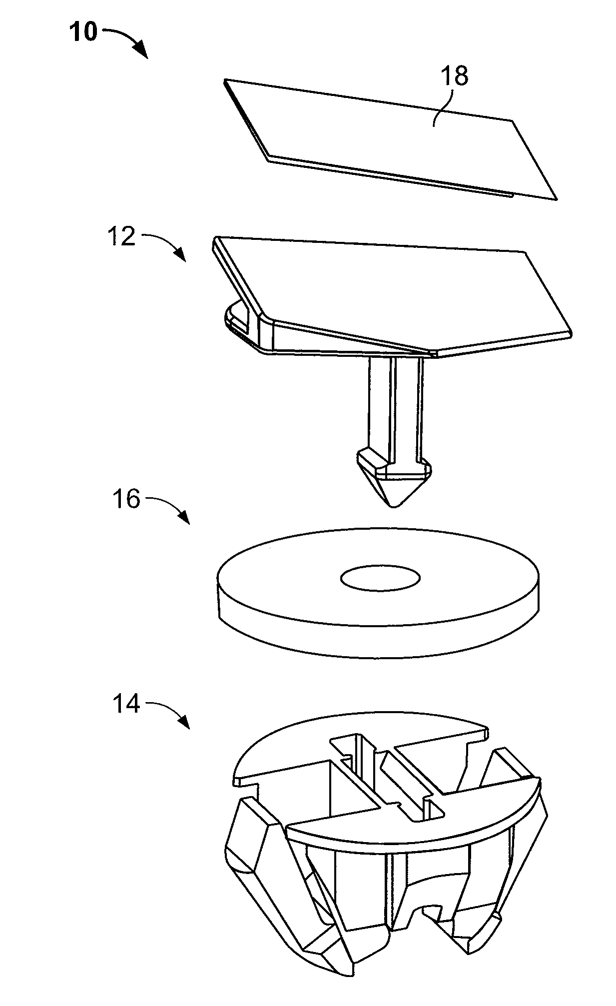
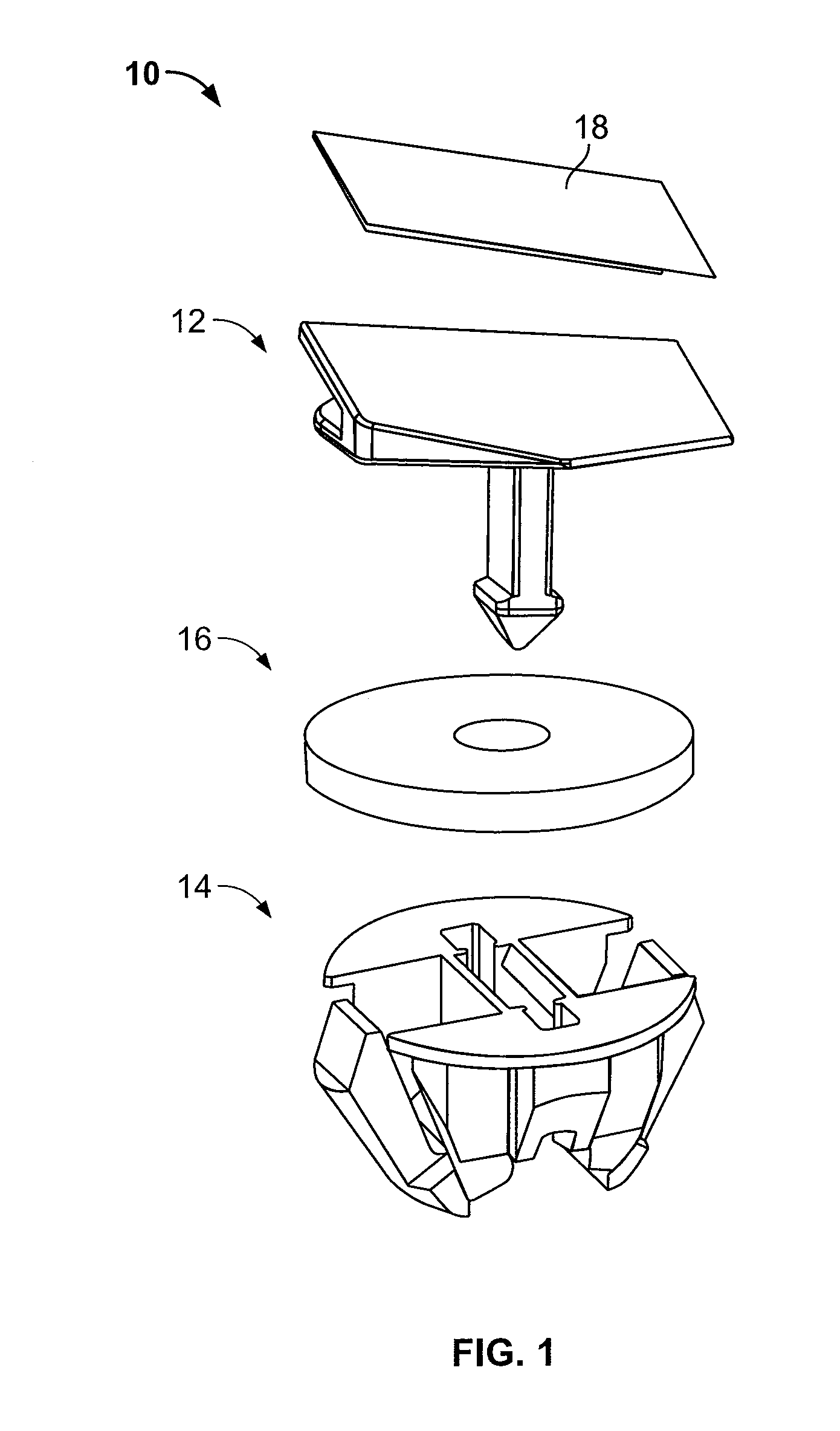
[0030]FIG. 1 illustrates an isometric exploded view of a fastener assembly 10 according to an embodiment of the present invention. The fastener assembly 10 includes a pin 12 configured to be adjustably secured to a grommet 14. The fastener assembly 10 may also include a circular seal 16 sandwiched between the pin 12 and the grommet 14 and adhesive tape 18 secured to a top portion of the pin 12.

[0031]The tape 18 is configured to adhesively secure the pin 12 to a panel, such as a B-pillar appliqué. Optionally, the pin 12 may secure to a panel through various other fastening techniques. For example, the pin 12 may be configured to snapably secure within a hole of a panel.

[0032]The grommet 14 is configured to adjustably retain the pin 12. The grommet is also configured to snapably secure within a hole formed through another panel. As such, the pin 12 secures to a first panel, while the grommet secures to a second panel. Because the pin 12 is configured to be adjustably secured within th...


PUM


Abstract

A fastener assembly configured to secure a first panel to a second panel includes a pin and a grommet. The pin includes a shaft connected to a tip. The grommet is configured to snapably secure into a hole of a panel. The grommet includes a central passage. The shaft is adjustably secured within the central passage, such that the shaft is allowed to shift a fixed distance within the central passage in a first direction, but is locked in place in the central passage with respect to a second direction that is perpendicular to the first direction.

Description

RELATED APPLICATIONS[0001]This application relates to and claims priority benefits from U.S. Provisional Patent Application No. 60 / 925,218 entitled “Pin and Grommet Fastener Assembly,” filed Apr. 19, 2007, which is hereby incorporated by reference in its entirety.FIELD OF THE INVENTION[0002]Embodiments of the present invention generally relate to a fastener assembly, and more particularly to a pin and grommet fastener assembly configured to secure panels together.BACKGROUND OF THE INVENTION[0003]Various applications include a first panel secured to a second panel. For example, cover panels, such as B-pillar appliqués, may be secured to automobiles include door frames or panels.[0004]In order to secure the appliqué to the door panel, a pin and grommet fastener may be used. The fastener typically includes a pin secured within a grommet. A top, planar portion of the pin may be adhesively secured to the appliqué, while the grommet is snapably secured within a hole formed in the door fra...

Claims


Application Information

Patent Timeline
Patent Type & Authority Applications(United States)
IPC IPC(8): F16B13/06
CPCB62D29/048F16B5/0657Y10T24/309Y10T24/42F16B5/126
Inventor SCROGGIE, DEREKOSTERLAND, ROBERTJAGODA, AARON
Owner ILLINOIS TOOL WORKS INC
Why Eureka
Try Eureka