
Vacuum Cleaner

a vacuum cleaner and vacuum cleaner technology, applied in the field of vacuum cleaners, can solve the problems of increased vacuum cleaner manufacturing cost and difficulty for users to operate the vacuum cleaner

Inactive Publication Date: 2008-10-30
SAMSUNG GWANGJU ELECTRONICS CO LTD
View PDF14 Cites 76 Cited by
  • Summary
  • Abstract
  • Description
  • Claims
  • Application Information

AI Technical Summary

Benefits of technology

[0017]The main gear may have more teeth than the sub gear for rotating the compressing plate to exceed an angle at which the lever is rotated.

Problems solved by technology

However, a conventional dust separating unit has the structure for dust compression irrespective of the structure for detachment and attachment, such that a vacuum cleaner having the dust separating unit has a complex structure, and fabricating cost of the vacuum cleaner is increased.
Additionally, it is difficult for a user to operate the vacuum cleaner.

Method used


Image

  • Vacuum Cleaner
  • Vacuum Cleaner
  • Vacuum Cleaner

Examples


Embodiment Construction

[0030]Certain exemplary embodiments of the present disclosure will now be described in greater detail with reference to the accompanying drawings.

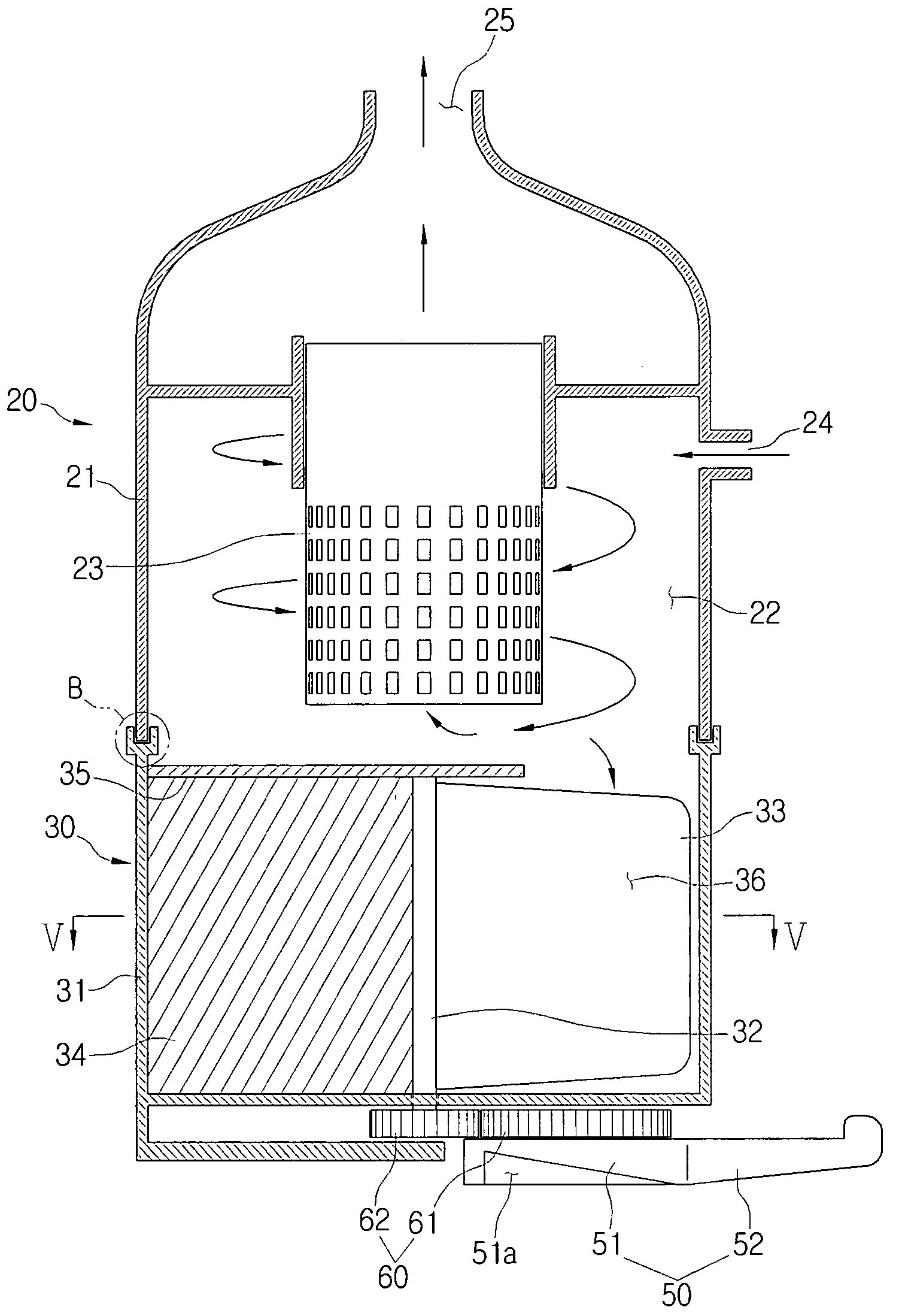
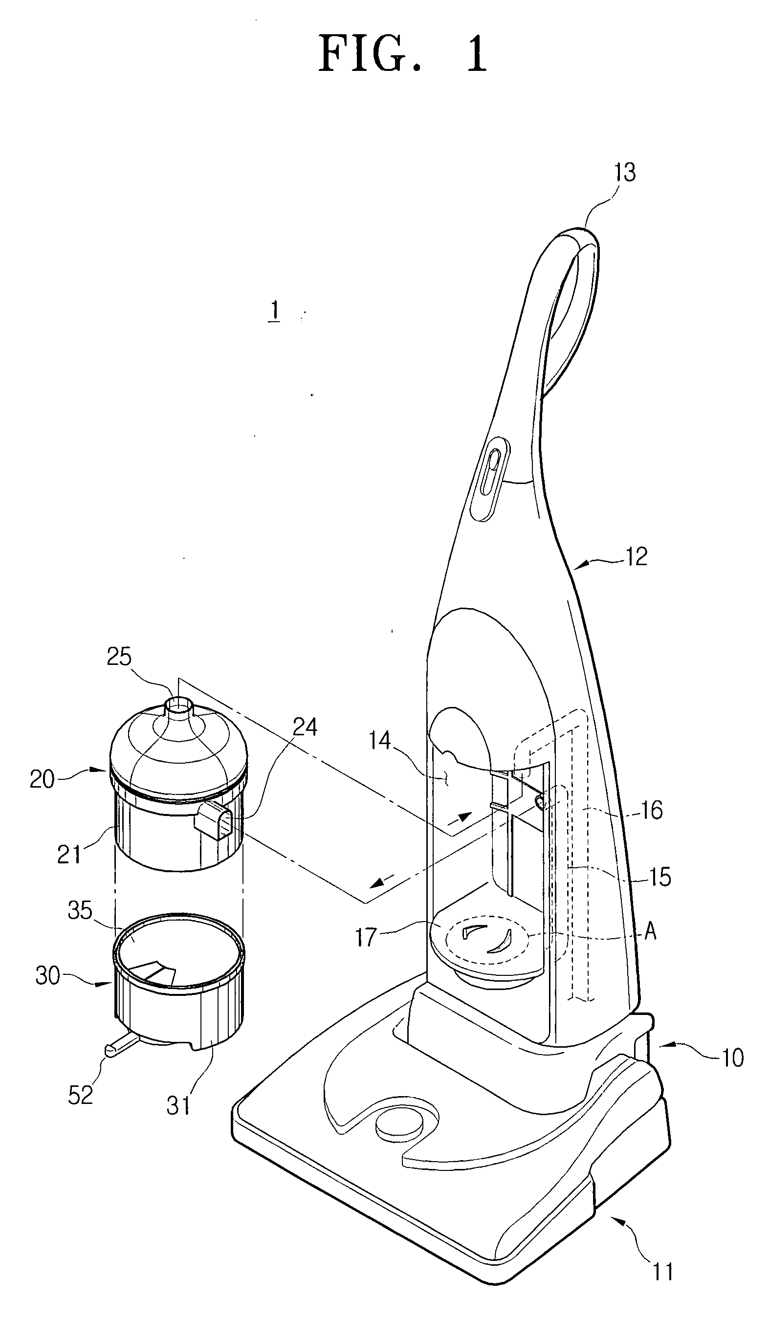
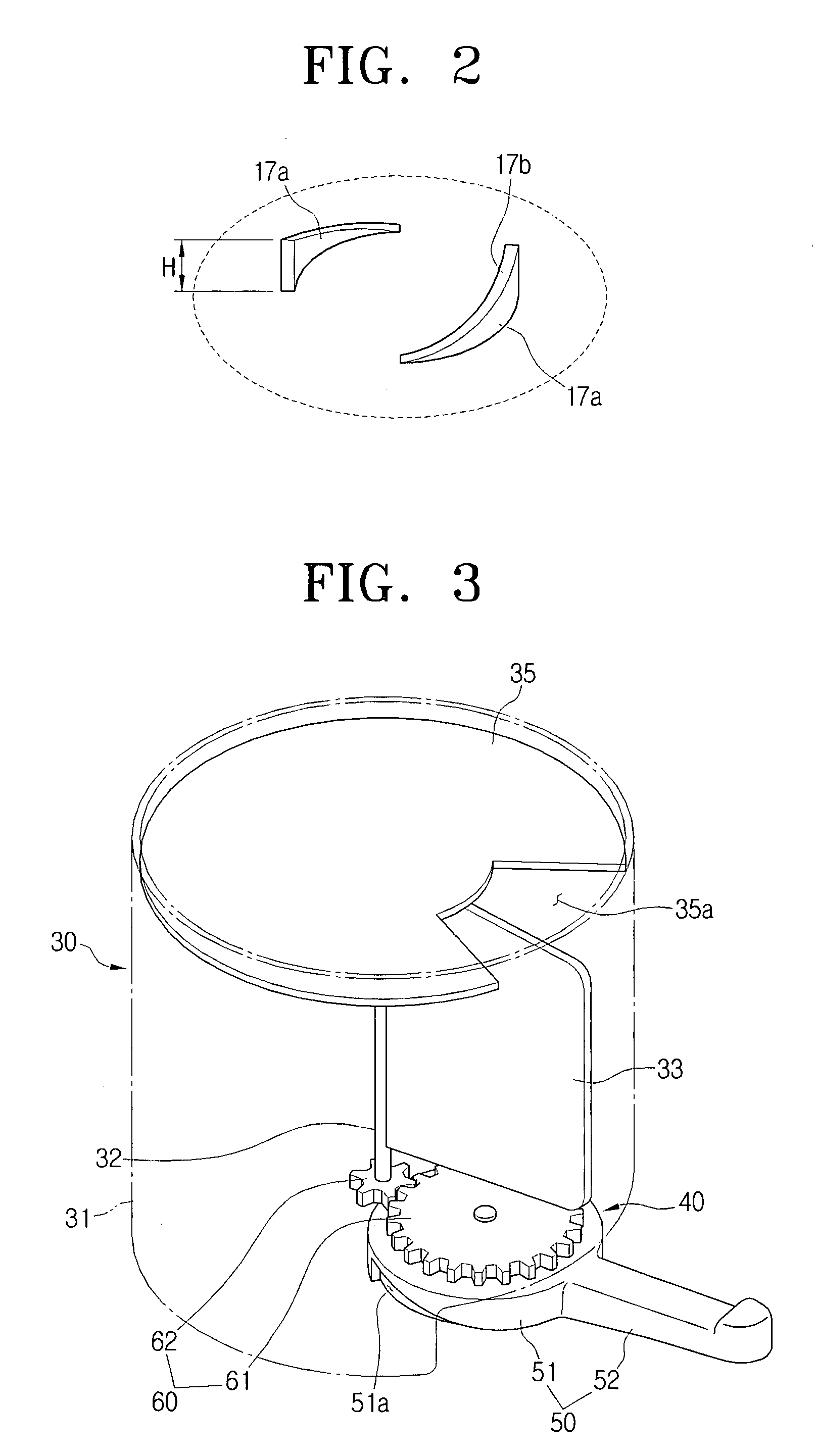
[0031]FIG. 1 is a fragmentarily exploded perspective view illustrating a vacuum cleaner according to an exemplary embodiment of the present disclosure, FIG. 2 is an enlarged perspective view illustrating a part A of FIG. 1, FIG. 3 is a perspective view illustrating a dust separating unit and a driving unit mounted in the vacuum cleaner of FIG. 1, FIG. 4 is a sectional view illustrating a cyclone unit mounted on the vacuum cleaner of FIG. 1 and a dust separating unit provided therein.

[0032]Referring to FIGS. 1 to 4, a vacuum cleaner 1 according to an exemplary embodiment of the present disclosure may comprise a vacuum cleaner body 10, a cyclone unit 20, a dust separating unit 30, and a driving unit 40.

[0033]The vacuum cleaner body 10 may comprise a horizontal body 11 at the bottom, and a vertical body 12 which is engaged substantially perpe...


PUM

PropertyMeasurementUnit
shapeaaaaaaaaaa
rotating forceaaaaaaaaaa
rotating force transferaaaaaaaaaa

Abstract

A vacuum cleaner includes a vacuum cleaner body, a cyclone unit which is mounted at the vacuum cleaner body, and separates dust from drawn air, a dust separating unit which is engaged with a lower end of the cyclone unit, said dust separating unit being configured to collect separated dust, said dust separating unit being detachable from the cyclone, and said dust separating unit comprising a compressing plate compressing the collected dust; and a driving unit which is disposed at a lower end of the dust separating unit, said driving unit being configured to ascend and descend the dust separating unit to be detachably connected to the cyclone unit and drives the compressing plate. As a result, the vacuum cleaner is capable of not only compressing dust in a dust separating unit by rotating a lever, but also detachably mounting the dust separating unit to a cyclone unit. Therefore, the vacuum cleaner having simplified structure and a convenient operation is provided.

Description

CROSS-REFERENCE TO RELATED APPLICATIONS[0001]This application claims priority under 35 U.S.C. § 119 from Korean Patent Application No. 10-2007-0059500, filed on Jun. 18, 2007, with the Korean Intellectual Property Office, and U.S. provisional Application No. 60 / 926,832, filed Apr. 30, 2007, with the United States Patent and Trademark Office, the entire disclosure of which is hereby incorporated by reference.BACKGROUND OF THE INVENTION[0002]1. Field of the Invention[0003]The present disclosure relates to a vacuum cleaner, and more particularly, to a vacuum cleaner capable of not only compressing dust in a dust separating unit, but also detachably mounting the dust separating unit to a cyclone unit by rotating manipulation of a lever.[0004]2. Description of the Related Art[0005]A vacuum cleaner draws in air and dust from a surface to be cleaned using the suction force.[0006]Dust is separated from the drawn air and is collected in a space, in the interior of the vacuum cleaner. Various...

Claims


Application Information

Patent Timeline
Patent Type & Authority Applications(United States)
IPC IPC(8): B01D45/12B01D45/18
CPCA47L5/28Y10S55/03A47L9/1683A47L9/108
Inventor OH, JANG-KEUNCHA, SEUNG-YONGKIM, MIN-HAKIM, HYOUN-SOOLEE, HYUN-JU
Owner SAMSUNG GWANGJU ELECTRONICS CO LTD
Features
  • Generate Ideas
  • Intellectual Property
  • Life Sciences
  • Materials
  • Tech Scout
  • Unparalleled Data Quality
  • Higher Quality Content
  • 60% Fewer Hallucinations
Learn More