

Patient couch apparatus, diagnostic imaging apparatus, and method of operating patient couch apparatus
a couch apparatus and patient technology, applied in the field of patient couch apparatus, diagnostic imaging apparatus, and method of operating patient couch apparatus, can solve the problems of difficult to change the orientation of the stretcher, difficult to transfer the subject without, and difficult to move the subject withou
- Summary
- Abstract
- Description
- Claims
- Application Information
AI Technical Summary
Problems solved by technology
Method used
Image

Examples
first embodiment
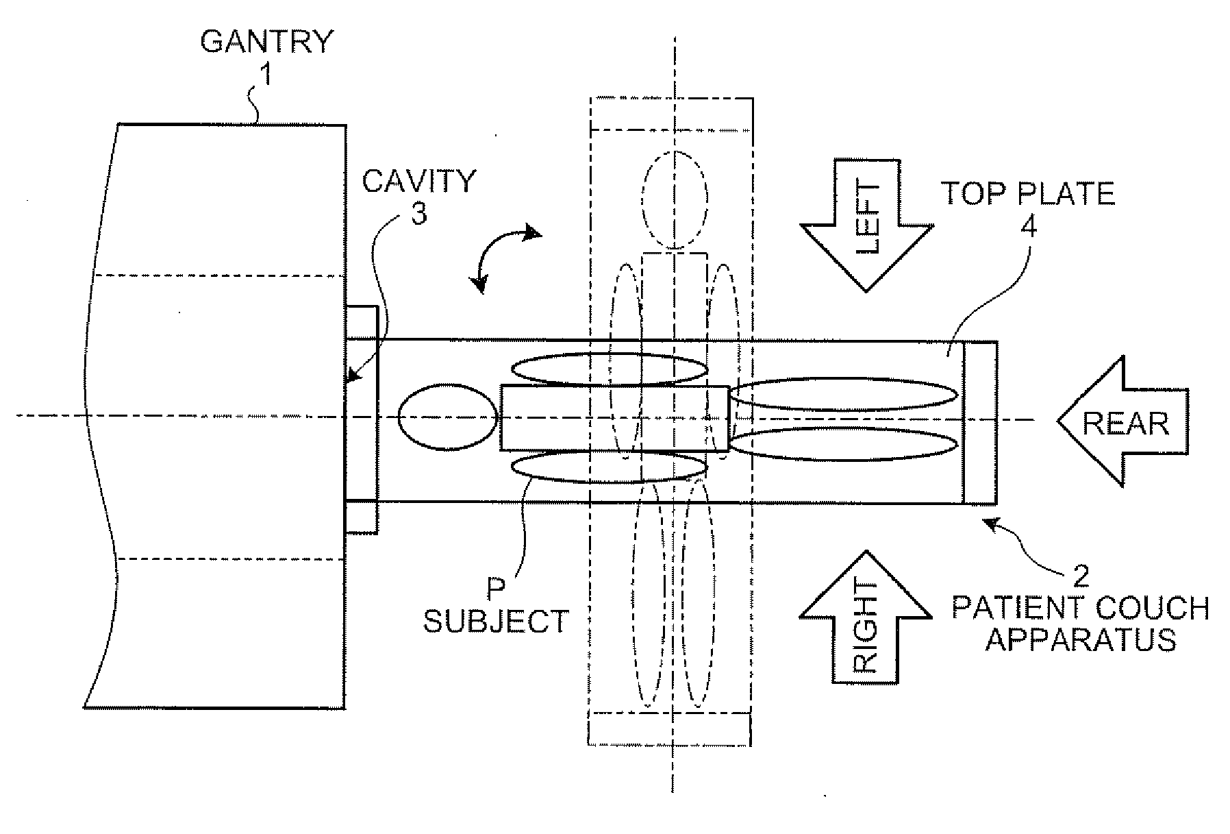
[0047]As described above, the MRI apparatus allows to lay the subject P on the top plate 4 easily even when a direction, along which the subject P approaches the patient couch apparatus 2, is limited.
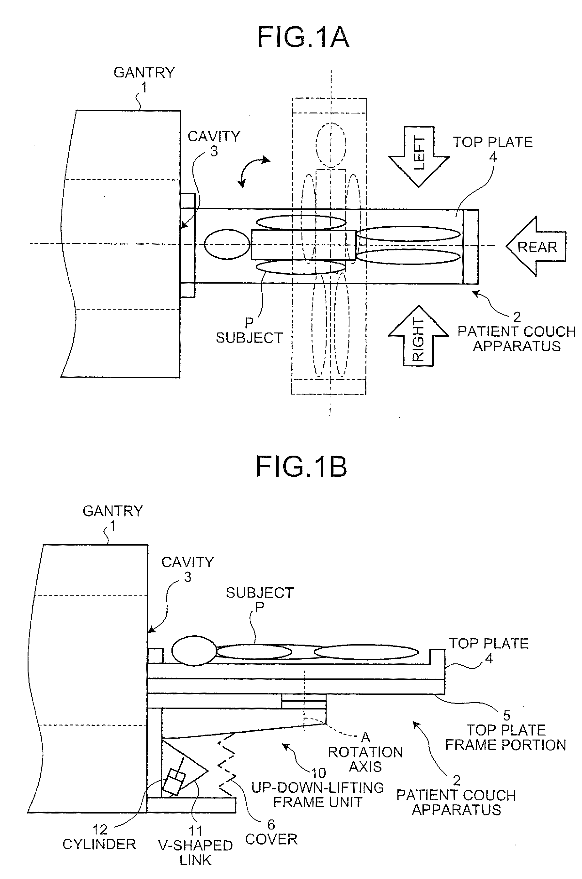
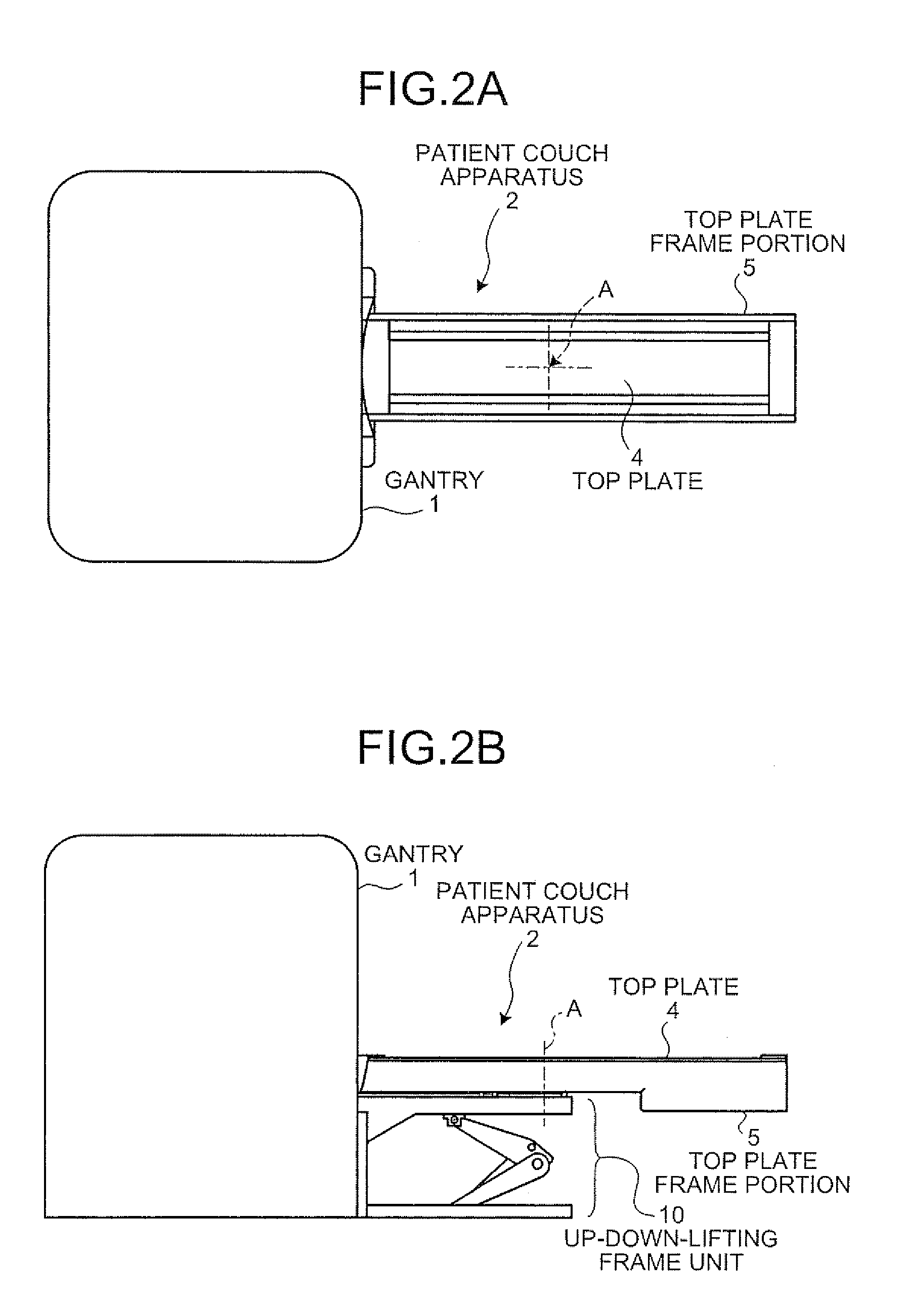
[0048]The overall configuration of the MRI apparatus according to the first embodiment will be described below. FIGS. 2A, 2B, and 2C are external views of the overall configuration of the MRI apparatus according to the first embodiment, in which FIG. 2A is a top view, FIG. 2B is a side view, and FIG. 2C is a front view. As shown in FIGS. 2A, 2B, and 2C, the MRI apparatus includes the gantry 1 and the patient couch apparatus 2.
[0049]The gantry 1 has the cavity 3 to receive the subject P inserted thereinto. The gantry 1 also has a static-magnetic-field magnet (not shown) that generates a static magnetic field in the imaging region in the cavity 3, gradient-magnetic-field coils (not shown) that generate gradient magnetic fields, and an RF transmitter (not shown) that irradiates RF pulses ...
second embodiment
[0079]While the V-shaped link 11 and the cylinder 12 are used as the up-down lifting mechanism that moves the top plate frame portion 5 vertically in the description on the first embodiment, the present invention is not limited thereto, and the up-down lifting mechanism can be implemented using a lead screw that has a thread on an outer circumferential surface thereof. Another configuration that uses such a lead screw will be descried below as the present invention.
[0080]For convenience of explanation, function units that have functions similar to those in the first embodiment with reference to the drawings will be denoted by like reference numerals, and descriptions thereof will be omitted.
[0081]The overall configuration of an MRI apparatus according to the second embodiment will be described first. FIGS. 8A, 8B, and 8C are external views illustrating the overall configuration of the MRI apparatus according to the second embodiment, in which FIG. 8A is a top view, FIG. 8B is a side...
third embodiment
[0091]First, transfer of the top plate 4 from the stretcher 30 to the patient couch apparatus 2 will be described. FIGS. 11 to 15 are first to fifth diagrams of the transfer of the top plate 4 from the stretcher 30 to the patient couch apparatus 2 of the MRI apparatus according to the FIGS. 11 to 15 depict the patient couch apparatus 2 with the top plate frame portion 5 having already been positioned to have a rotation angle of approximately 90 degrees.
[0092]FIG. 11 depicts configurations of the MRI apparatus and the stretcher 30 according to the third embodiment. As shown in FIG. 11, the stretcher 30 is constructed by removing the top plate 4 from the patient couch apparatus 2 and attaching the top plate 4 to a trolley 31 on casters 32.
[0093]FIG. 12 is a schematic diagram for explaining the top plate 4 being attached to the trolley 31, depicting portions, at which the top plate 4 is attached to the trolley 31. As shown in FIG. 12, a predetermined number of hooks 33 are provided on...
PUM
 Abstract
Description
Claims
Application Information