Top unloading fixed line trimmer head

a technology of fixed line and trimmer head, which is applied in the field of vegetable trimmer, can solve the problems of time and effort of operator, head jamming, and advancements that have met with some resistan

Inactive Publication Date: 2008-11-06
ALLISS GEORGE E
View PDF20 Cites 30 Cited by
  • Summary
  • Abstract
  • Description
  • Claims
  • Application Information

AI Technical Summary

Benefits of technology

[0021]Since the end of the fixed length of line exits from the “top” side instead of the “bottom” side of the trimmer head, a ground spacer can be utilized that defines and regulates a cutting distance of the trimmer line at which the trimmer head can glide and / or ride upon the ground surface freely. Additionally, significantly less debris (e.g., no debris) clogs the exit ports of the trimmer head.

Problems solved by technology

While this evolution of the flexible line rotary trimmers from the manual head to the automatic head has significantly reduced operator time and effort in replacing worn and broken line, these advancements have met with some resistance.
For the casual home user of a trimmer machine this is a problem, because the trimmer head in most cases must be disassembled in order to correct problems.
The tangling may be caused by the improper winding of trimmer line onto the spool, and / or the occurrence of the accumulation of line welds, excess dirt and debris within the trimmer head.
The excess dirt and debris may also cause the head to jam.
If the trimmer line is not wrapped properly around the spool, the trimmer line may tangle within the trimmer head, and may interfere with the withdrawal of fresh trimmer line.
Disassembly, winding of the spool, and reassembly of the trimmer head is cumbersome and requires a certain amount of dexterity and patience by the average operator, which makes the trimmer head difficult to use.
The more complicated the trimmer line feed mechanism; the more critical the proper winding of the trimmer line within the head becomes.
In some of these fixed line cutting heads removal of the worn trimmer line to replace it with a new fixed length of trimmer line can be difficult because the trimmer line is “jammed or wedged” so tight that a tool may be needed to aide in unjamming the trimmer line to be able to remove the trimmer line from the trimmer head.
While such a trimmer head and trimmer line configuration provides for relatively simple trimmer line replacement, each length of replacement trimmer line must be provided with a suitable enlarged member at one end thereof, significantly increasing the cost of operation.
In addition, if the trimmer line were to break at the eyelet or outlet end of the trimmer line channel, trimmer line removal may be difficult.
In the Fogle '618 patent, the fixed line trimmer head requires both loading and unloading of the fixed length of trimmer line from the underside (which is the bottom) of the trimmer head housing, thus causing the trimmer head to be subject to the disadvantage of an awkward bottom unloading of trimmer line.
One problem is that unloading the trimmer line from the bottom of the trimmer head, at least makes difficult and may preclude the utilization of a replaceable ground spacer that defines and regulates a cutting distance of the trimmer line from the ground surface.
A problem with grasping and gripping the end of the trimmer line by hand from the underside of the trimmer head to unload the trimmer line as shown in one or more embodiments of Iacona '666; '424; and '328; Alliss '292; Proulx '857 and Brant '455 is that the trimmer line is not easily accessible to an end user.
The inaccessibility of the trimmer line makes it difficult to unload worn out fixed length trimmer lines and load new fixed lengths trimmer lines from the loading port located at the periphery of the vegetation trimmer.
It may be that during use, a vacuum is created, which may result from the large central opening in the cover.
The vacuum may be adjacent the bottom cover of the head, which makes uniform cutting of vegetation more difficult.
Another issue with prior art trimmer heads, which the present inventors have recognized as a problem, is when one trimmer line of a two line head breaks off from the trimmer head, the vegetation trimmer will vibrate at a high frequency, because the trimmer head is unbalanced.

Method used


Image

  • Top unloading fixed line trimmer head
  • Top unloading fixed line trimmer head
  • Top unloading fixed line trimmer head

Examples


Embodiment Construction

[0048]Although various embodiments of the invention may have been motivated by various deficiencies with the prior art, which may be discussed or alluded to in one or more places in the specification, the embodiments of the invention do not necessarily address any of these deficiencies. In other words, different embodiments of the invention may address different deficiencies that may be discussed in the specification. Some embodiments may only partially address some deficiencies or just one deficiency that may be discussed in the specification, and some embodiments may not address any of these deficiencies.

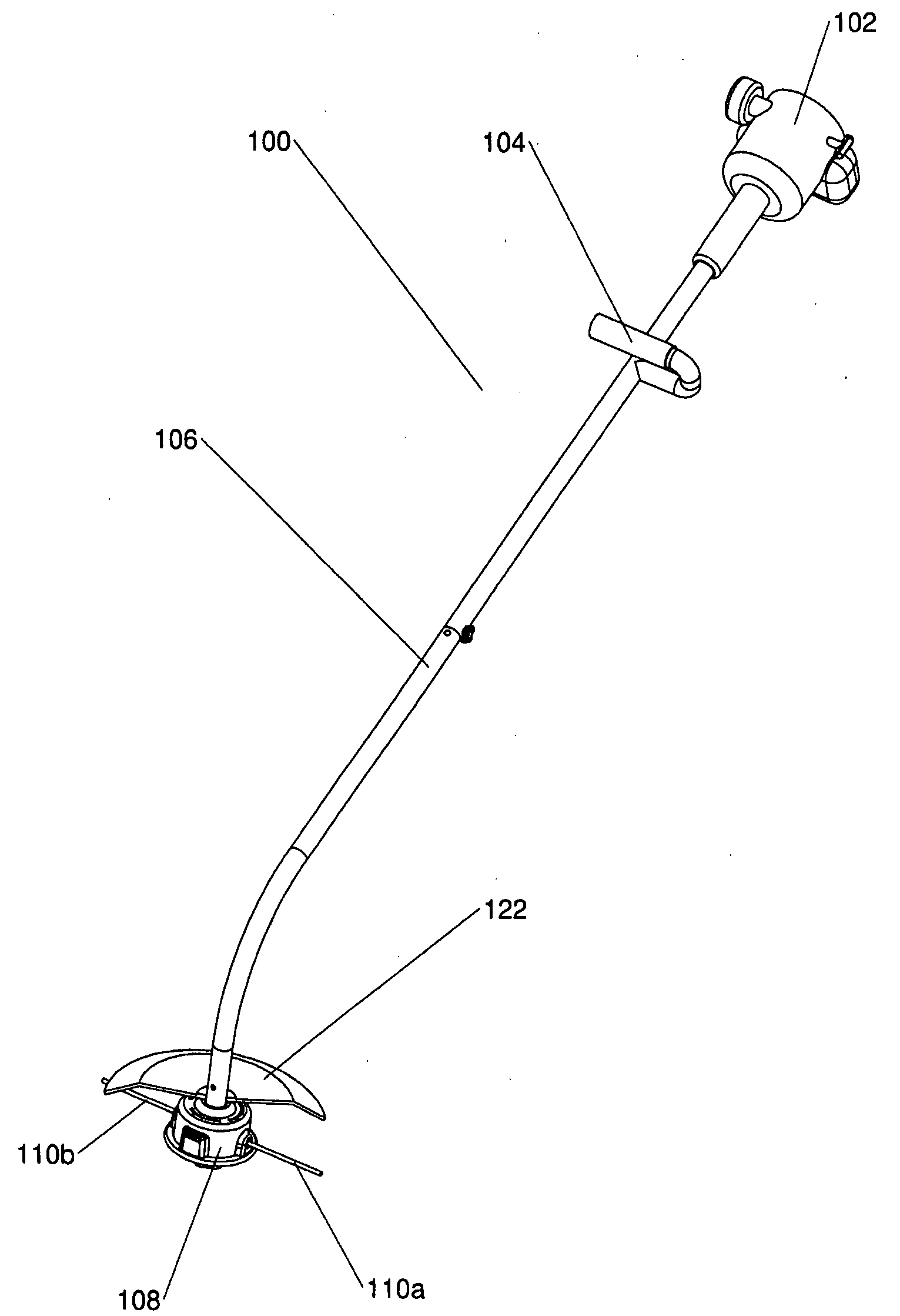
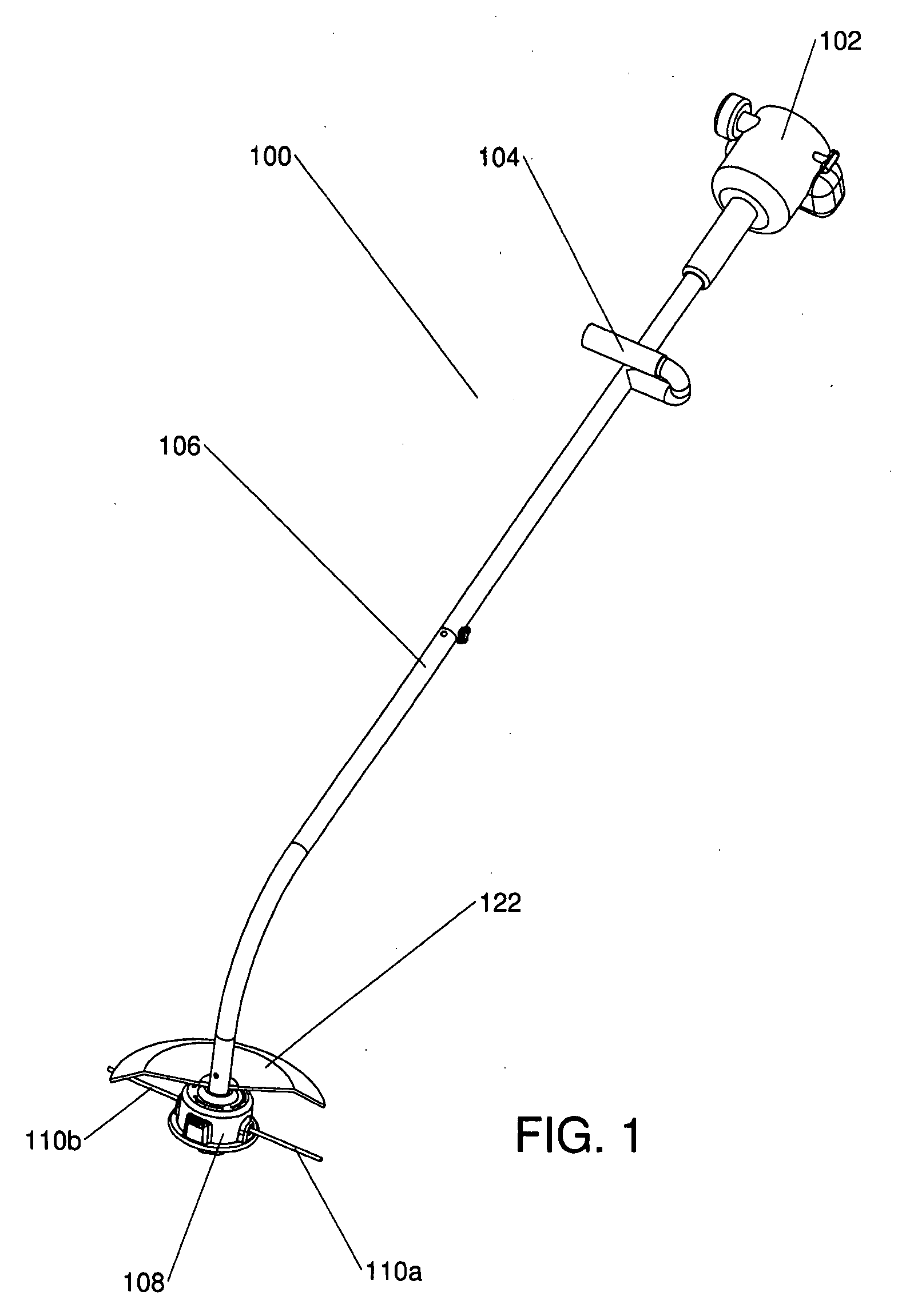
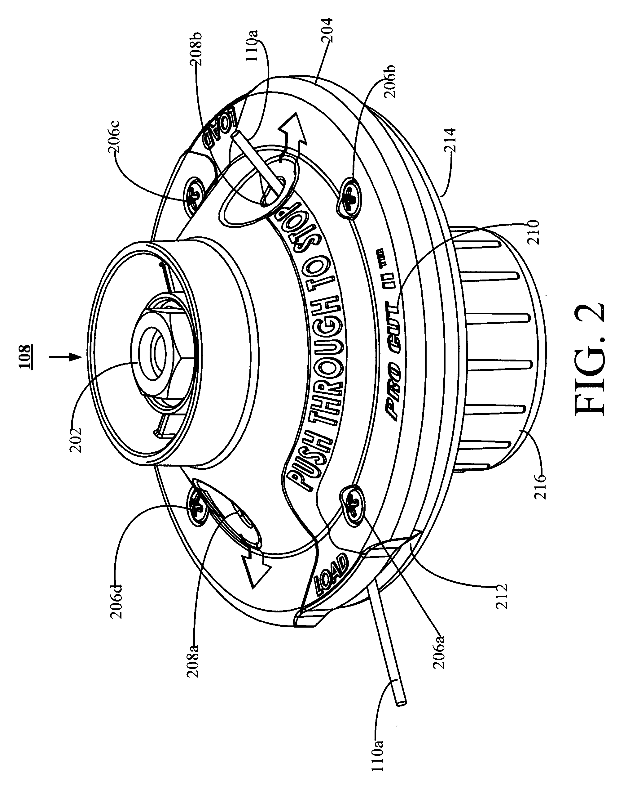
[0049]In general, at the beginning of the discussion of each of FIGS. 1-8 and 11B-16 is a brief description of each element, which may have no more than the name of each of the elements in the one of FIGS. 1-8 and 11B-16 that is being discussed. After the brief description of each element, each element is further discussed in numerical order. In general, each of FIGS. 1-16 is disc...


PUM


Abstract

In an embodiment, a fixed line trimmer head is configured such that the trimmer head is not loaded or unloaded from the bottom. In an embodiment, the trimmer head is loaded from the periphery and unloaded from the top.In and embodiment, the trimmer head may include a gripping mechanism that is located near enough to the center of the trimmer head such that if the trimmer line breaks, the trimmer head does not become imbalanced to the point of vibrating.In an embodiment, a spacer is located below the trimmer head. In an embodiment, the spacer has a socket that is contoured to mate with a bolt head. The bolt is inserted into the socket, and through a hole at the bottom of the socket. As a result of the contoured socket, the spacer may be used instead of a wrench to screw the bolt to trimmer head.

Description

CROSS-REFERENCE TO RELATED APPLICATIONS[0001]This application claims priority benefit of U.S. Provisional Patent Application No. 60 / 924,120, filed May 1, 2007, which is incorporated herein by reference.FIELD[0002]The present invention is related to vegetation trimmers that use flexible trimmer line in general.BACKGROUND[0003]The subject matter discussed in the background section should not be assumed to be prior art merely as a result of its mention in the background section. Similarly, a problem mentioned in the background section or associated with the subject matter of the background section should not be assumed to have been previously recognized in the prior art. The subject matter in the background section merely represents different approaches, which in and of themselves may also be inventions.[0004]Flexible line rotary trimmers are commonly used for cutting vegetation such as grass and weeds, particularly along walks, fences, flower beds, and around trees. Flexible line rota...

Claims


Application Information

Patent Timeline
Patent Type & Authority Applications(United States)
IPC IPC(8): A01D34/00
CPCA01D34/4166
Inventor ALLISS, GEORGE E.
Owner ALLISS GEORGE E
Why Eureka
Try Eureka