Display device, display driver and image display method

Inactive Publication Date: 2008-11-06
SYNAPTICS JAPAN GK
View PDF19 Cites 87 Cited by
  • Summary
  • Abstract
  • Description
  • Claims
  • Application Information

AI Technical Summary

Benefits of technology

[0051]On the display screen of the cellular phone, digital camera, and the like, the natural image and the icon including a large number of high-luminance pixels are often displayed simultaneously as described above, and the expected power consumption reduction effect cannot be achieved in some cases by the conventional backlight control method.
[0052]Therefore, an object of the present invention is to provide, in an image display device in which image quality degradation for pixels is allowed to a certain extent and the backlight emission amount is correspondingly reduced to achieve the power saving, a drive circui

Problems solved by technology

In the technique of Japanese Patent Application Laid-Open Publication No. 11-65531, however, in the method of performing the data extension and the backlight control using the maximum value of the grayscale of the display image: x, if even one pixel of the maximum grayscale (255 grayscale) of the liquid crystal display device is c

Method used


Image

  • Display device, display driver and image display method
  • Display device, display driver and image display method
  • Display device, display driver and image display method

Examples


Example

First Embodiment

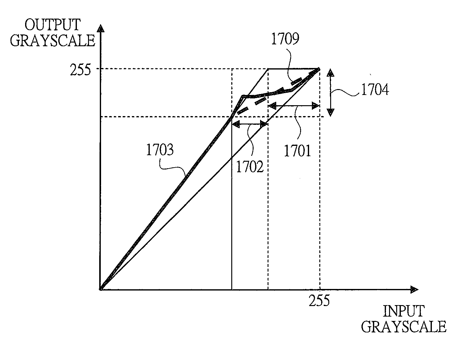
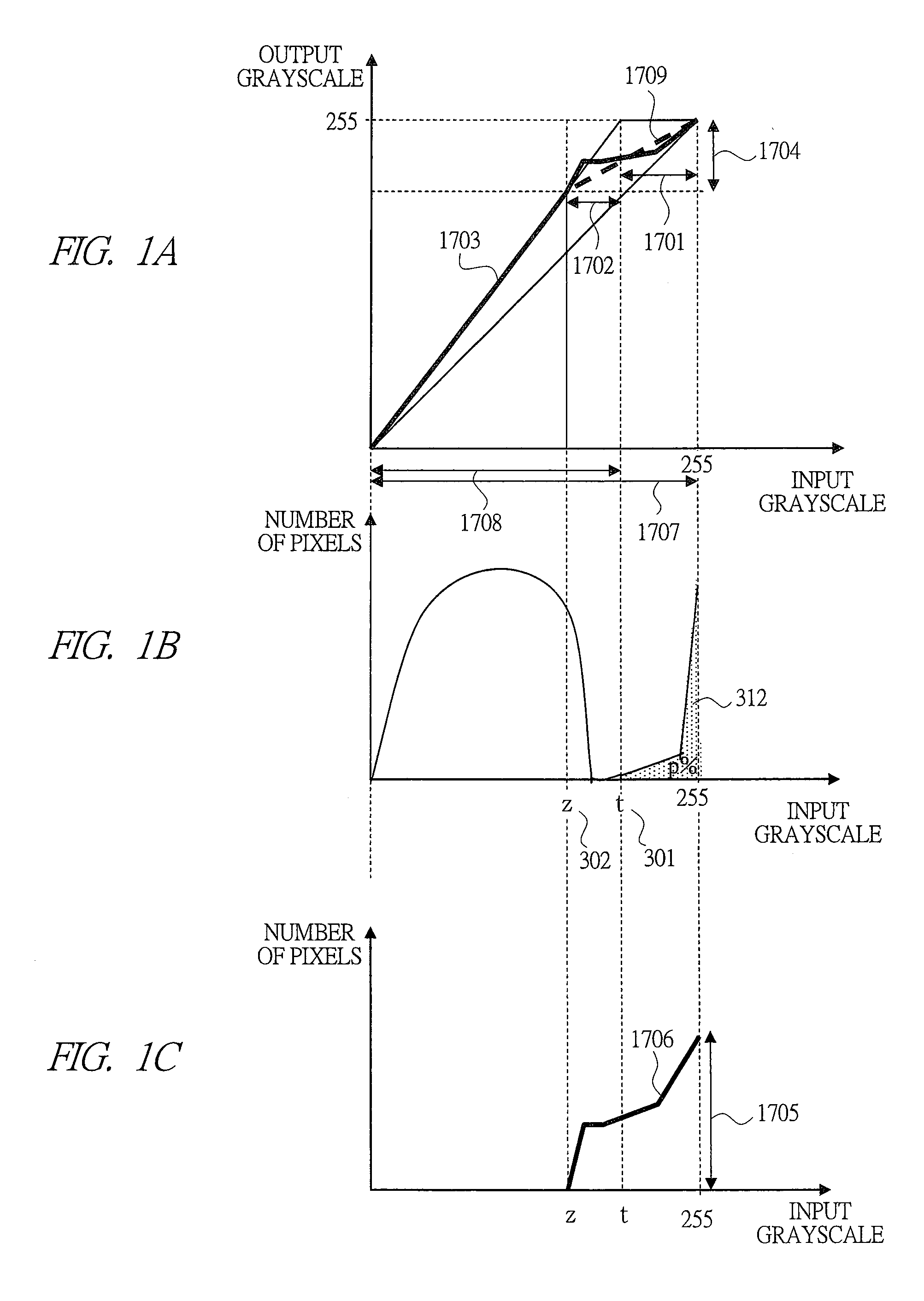
[0125]First, the outline of an image grayscale extending process performed in the display driver according to a first embodiment of the present invention will be described briefly with reference to FIG. 1. In the present embodiment, the operation shown in FIG. 1 is performed to lower to the backlight power. FIG. 1A is a view showing a relationship of input grayscale and output grayscale of the display driver of the present embodiment. FIG. 1B is a view showing a histogram of the display image. As shown in FIG. 1B, in the display image, the t grayscale 301 at which the number of pixels of the t grayscale 301 or higher and the maximum grayscale (255 grayscale) or lower is p % 312 of the total number of pixels is referred to as a threshold grayscale t301. In FIG. 1B, a grayscale z302 between the grayscale 0 and the grayscale t will be considered.

[0126]In the present embodiment, the difference 1702 between the grayscale t and the grayscale z is controlled to be a constan...

Example

Second Embodiment

[0152]Next, a display device according to a second embodiment of the present invention will be described with reference to FIG. 3. In the first embodiment, a counter for each grayscale equal to or higher than the grayscale z is required and the circuit scale is large. The second embodiment is basically the same as the first embodiment, but a method capable of achieving the reduction in circuit scale will be described. FIG. 3B is the same as FIG. 1B and is a view showing a histogram of a display image.

[0153]In the present embodiment, the portion between the grayscale z and the maximum grayscale 255 is divided into four equal intervals 1601, 1602, 1603, and 1604. The boundary of 1601 and 1602 is z1, the boundary of 1602 and 1603 is z2, and the boundary of 1603 and 1604 is z3. The cumulative value N1 of the histogram from the grayscale z+1 to the grayscale z1, the cumulative value N2 of the histogram from the grayscale z+1 to the grayscale z2, the cumulative value N3 o...

Example

Third Embodiment

[0157]Next, a display device according to a third embodiment of the present invention will be described with reference to FIG. 4 to FIG. 7. FIG. 4 is a block diagram of the display device according to the third embodiment of the present invention. The third embodiment is substantially the same as the first embodiment, but differs in the extension arithmetic operation of the grayscale performed in the pixel extending circuit 109.

[0158]FIG. 5B is a view showing a histogram of a display image. As shown in FIG. 5B, in the display image, the t grayscale 301 at which the number of pixels having the grayscale values of the t grayscale 301 or higher and the maximum grayscale (255 grayscale) or lower is p % 312 of the total number of pixels is referred to as the threshold grayscale 301, and a point (t, z) 305 between the coordinate (t, maximum grayscale (255)) and the coordinate (t, t) on FIG. 5A will be considered.

[0159]In the present embodiment, when the grayscale value of ...


PUM


Abstract

In a display device and a display driver, when a grayscale of a display image is equal to or lower than a specific grayscale value obtained from a histogram of the display image, a display grayscale is extended with a linear function. On the other hand, when a grayscale of a display image is equal to or higher than the specific grayscale value, histogram equalization of a part higher than the specific grayscale value is performed, and the display grayscale is extended with a non-linear function obtained from the histogram equalization.

Description

CROSS-REFERENCE TO RELATED APPLICATION[0001]The present application claims priority from Japanese Patent Application No. 2007-114161 filed on Apr. 24, 2007, Japanese Patent Application No. 2007-164248 filed on Jun. 21, 2007, Japanese Patent Application No. 2007-164782 filed on Jun. 22, 2007, Japanese Patent Application No. 2007-248314 filed on Sep. 26, 2007, the contents of which are hereby incorporated by reference into this application.TECHNICAL FIELD OF THE INVENTION[0002]The present invention relates to a display device and a drive circuit thereof having a light source whose light amount is controllable and performing the display by controlling a transmissivity control element for controlling the transmissivity of light arranged on a front surface of the light source. More particularly, it relates to a display device using a liquid crystal element and a drive circuit thereof (for example, LSI).BACKGROUND OF THE INVENTION[0003]It is important to suppress the power consumption in ...

Claims


Application Information

Patent Timeline
IPC IPC(8): G09G3/36
CPCG09G3/3406G09G3/3611G09G2320/0276G09G2320/064G09G2320/0646G09G2320/0653G09G2320/066G09G2330/021G09G2360/145G09G2360/16G02F1/133G09G3/20G09G3/36
Inventor KUROKAWA, YOSHIKIKATAYAMA, YUKARIAWAKURA, HIROKITAKADA, NAOKIKUDO, YASUYUKIAKAI, AKIHITOTOSHIMI, GOKIAOYAMA, AKIHISASAKAMAKI, GORO
Owner SYNAPTICS JAPAN GK
Why Eureka
Try Eureka