Element loading mechanism and method

a loading mechanism and element technology, applied in the field of element loading mechanism and method, can solve the problems of not being able to secure the loader to a height-adjustable platform, but being placed on by the loader

Inactive Publication Date: 2008-12-18
HALLAN MATTHEW J +3
View PDF18 Cites 172 Cited by
  • Summary
  • Abstract
  • Description
  • Claims
  • Application Information

AI Technical Summary

Benefits of technology

[0009]A first embodiment of the present invention is a loader for moving a filter element from one to another of a loaded position and an unloaded position, each position being relative to an interior, element-receiving portion of a pressure vessel, the pressure vessel also having an exterior spaced apart from said interior so as to form a pressure vessel body, the pressure vessel body being secured in place by a support structure operatively connected to at least a surface portion of the pressure vessel exterior, the loader comprising a loader section and a connection section, the loader section having a section interconnect end, a distal end remote from the section interconnect end, and an element support structure, the element support structure spanning between, and being operatively connected to, each of the section interconnect and distal e

Problems solved by technology

Gottberg places the loader on, but does not sec

Method used


Image

  • Element loading mechanism and method
  • Element loading mechanism and method
  • Element loading mechanism and method

Examples


Embodiment Construction

[0020]Embodiments of the present disclosure will now be described in relation to the accompanying drawings, which will at least assist in illustrating the various features of the various embodiments. In the Figs, the first digit of a reference number refers to the Figure in which it is used, while the remaining two digits of the reference number refer to the same or equivalent parts of embodiment(s) of the present disclosure used throughout the several Figs of the drawings.

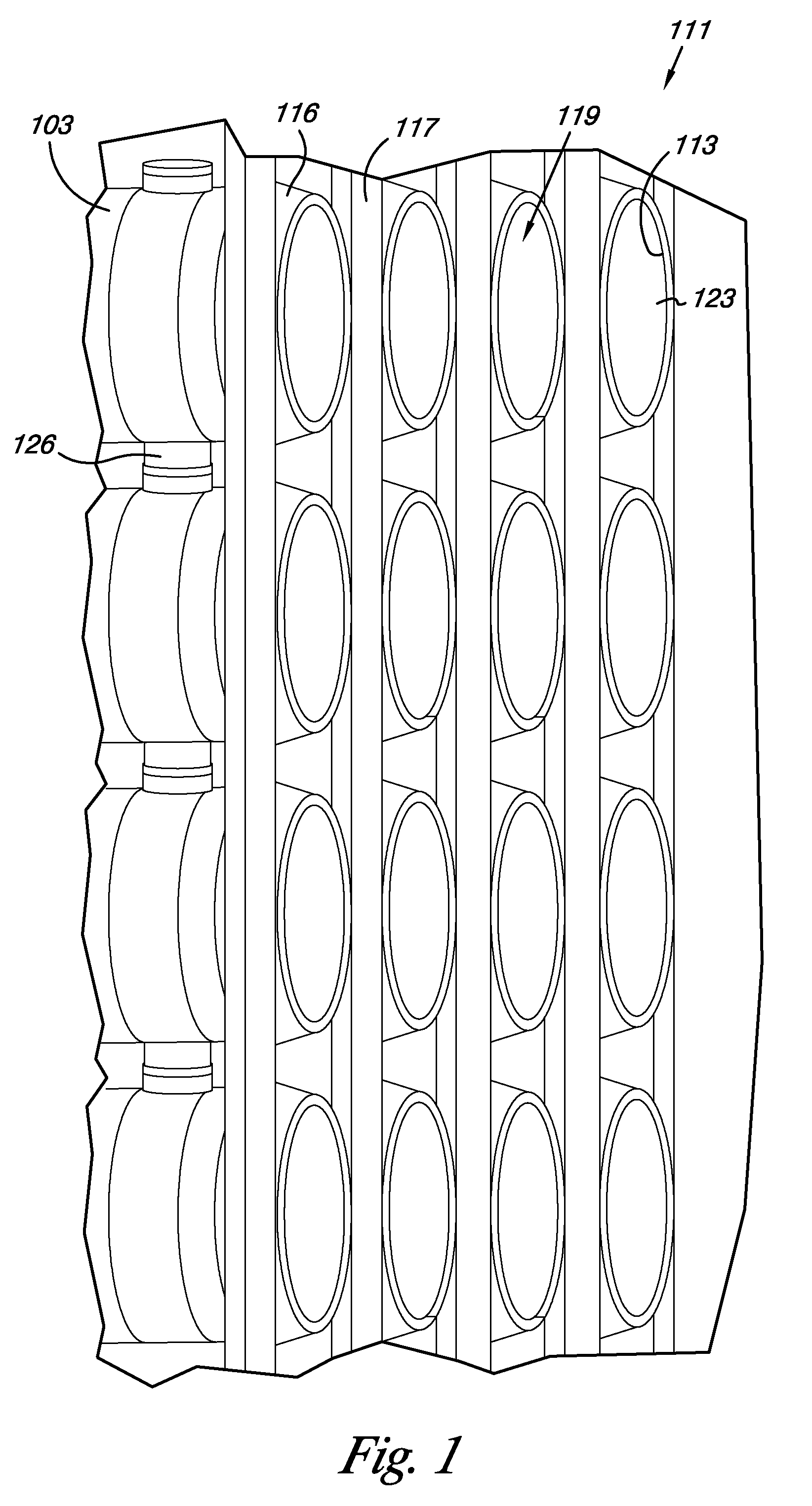
[0021]FIG. 1 shows one embodiment of a pressure vessel rack 111. Pressure vessel rack 111 comprises a support structure 117 and a plurality of pressure vessels 116. Each pressure vessel 116 has a first end 113, a second end (not shown), an inside 119 and an outside 103. Further, each pressure vessel defines an opening 123 through which a filter element (shown at 215 in FIG. 2B) may pass to be loaded into, desirably with a close-tolerance fit, a space defined by the inside 119 of pressure vessel 116 or unloaded fro...


PUM

PropertyMeasurementUnit
Pressureaaaaaaaaaa
Diameteraaaaaaaaaa

Abstract

A loader for moving a filter element between loaded and unloaded positions with respect to a pressure vessel is provided. The loader includes a connection section associated with a loader section. The connection section is operative to be secured in coaxial alignment with the pressure vessel. The loader section is operative to receive a filter element and move the filter element between the loaded and unloaded positions. The loader section includes a cradle assembly for supporting a filter element and a carriage assembly operative to engage the filter element and move it between the loaded and unloaded positions.

Description

[0001]This application claims the benefit of U.S. Provisional Application No. 60 / 874,452 filed Dec. 12, 2006.FIELD OF THE INVENTION[0002]The present invention relates to a loader assembly and a method for loading and unloading filter elements into or out of a pressure vessel.BACKGROUND OF THE INVENTION[0003]Pressure-driven fluid separation systems involve passing a fluid feed mixture across, for example a surface of a filter membrane or other structure adapted to act as a selective barrier. Such a barrier permits some components of the fluid feed mixture to pass through more readily than other components of said mixture.[0004]Commercial fluid separation processes use, for example, hollow fiber and spiral wound membrane arrangements. Spiral wound membranes provide a large, relative to hollow fibers, membrane contact area while permitting use of a rather small overall containment or pressure vessel. In a typical manufacturing process, one forms each spiral wound membrane (a rolled lam...

Claims


Application Information

Patent Timeline
IPC IPC(8): B01D35/30
CPCB01D29/96B01D63/10B01D65/00B01D67/0097
Inventor HALLAN, MATTHEW J.JOHNSON, JON E.PEERY, MARTIN H.JOHNSON, LANCE D.
Owner HALLAN MATTHEW J
Why Eureka
Try Eureka