Infrared-Transmitting Cover

a technology of infrared and transparent covers, applied in the direction of optical elements, lighting and heating apparatus, instruments, etc., can solve the problems of limiting the freedom of design when designing devices, double-sided adhesive sheets have the same disadvantages as black or dark colored resin window plates, and it is difficult to manufacture random resin window plates. , to achieve the effect of inhibiting the transmission of visible ligh

Inactive Publication Date: 2008-12-25
TOKAI OPTICAL CO LTD
View PDF13 Cites 54 Cited by
  • Summary
  • Abstract
  • Description
  • Claims
  • Application Information

AI Technical Summary

Benefits of technology

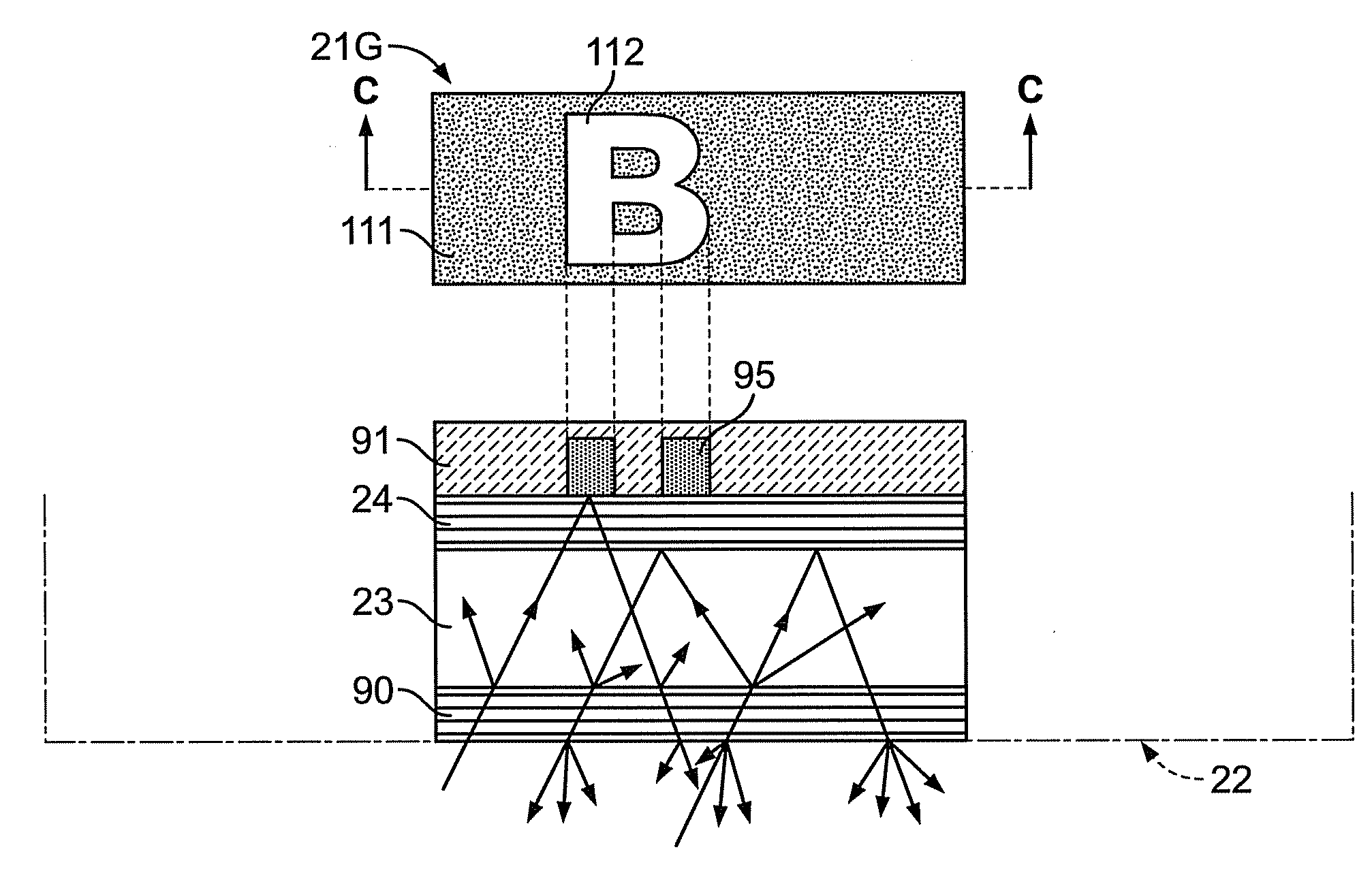
[0018]In one aspect, the cover is attached to an infrared signal port of an electronic device, and the cover includes an outer surface exposed outside the electronic device and an inner surface arranged inside the electronic device. The base layer is colorless and transparent and includes a first surface close to the inner surface of the cover and a second surface close to the outer surface of the cover. The dielectric multilayer film is laminated on the first surface of the base layer. The cover further includes a black layer laminated on the dielectric multilayer film, having infrared transparency, and inhibiting transmission of visible light. A diffusion layer is laminated on the second surface of the base layer.
[0019]In one aspect, the base layer is colorless and transparent and includes a first surface close to the inner surface of the cover and a second surface close to the outer surface of the cover. The dielectric multilayer film is laminated on the first surface of the base layer. The cover further includes an information printed layer laminated on the dielectric multilayer film. A black layer is laminated on the information printed layer, has infrared transparency, and inhibits transmission of visible light. A diffusion layer laminated on the second surface of the base layer.

Problems solved by technology

The black or dark colored resin window plate of the prior art may in some cases not match with the outer appearance of electronic device or electric device.
Thus, there is a limit to the freedom of designing when designing devices so that the black or dark colored resin window plate does not stand out.
Thus, the double-sided adhesive sheet has the same disadvantages as a black or dark colored resin window plate.
It is difficult to manufacture a resin window plate having a random appearance coloring while maintaining infrared transparency and shielding visible light.

Method used

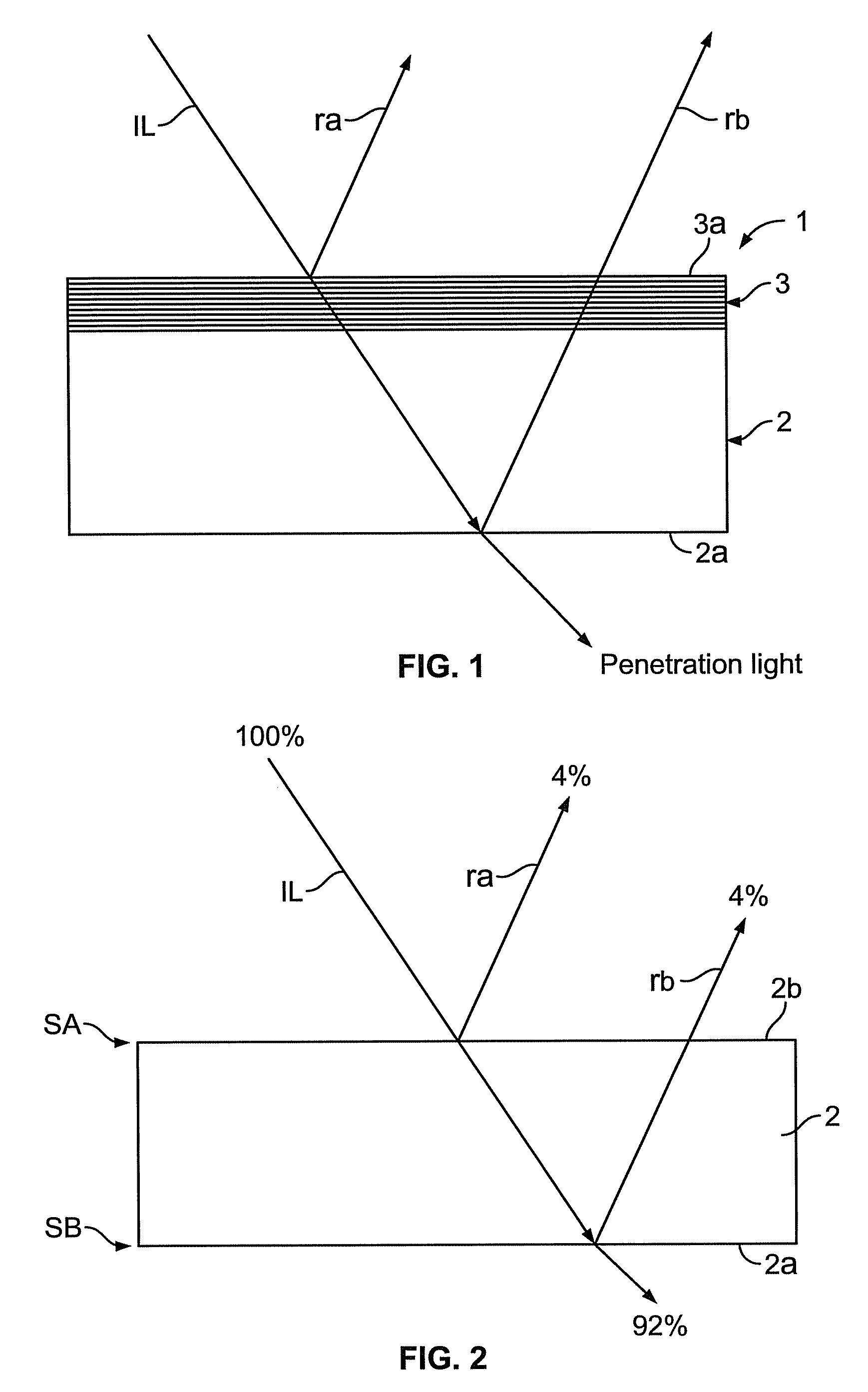

Image

  • Infrared-Transmitting Cover
  • Infrared-Transmitting Cover
  • Infrared-Transmitting Cover

Examples


first embodiment

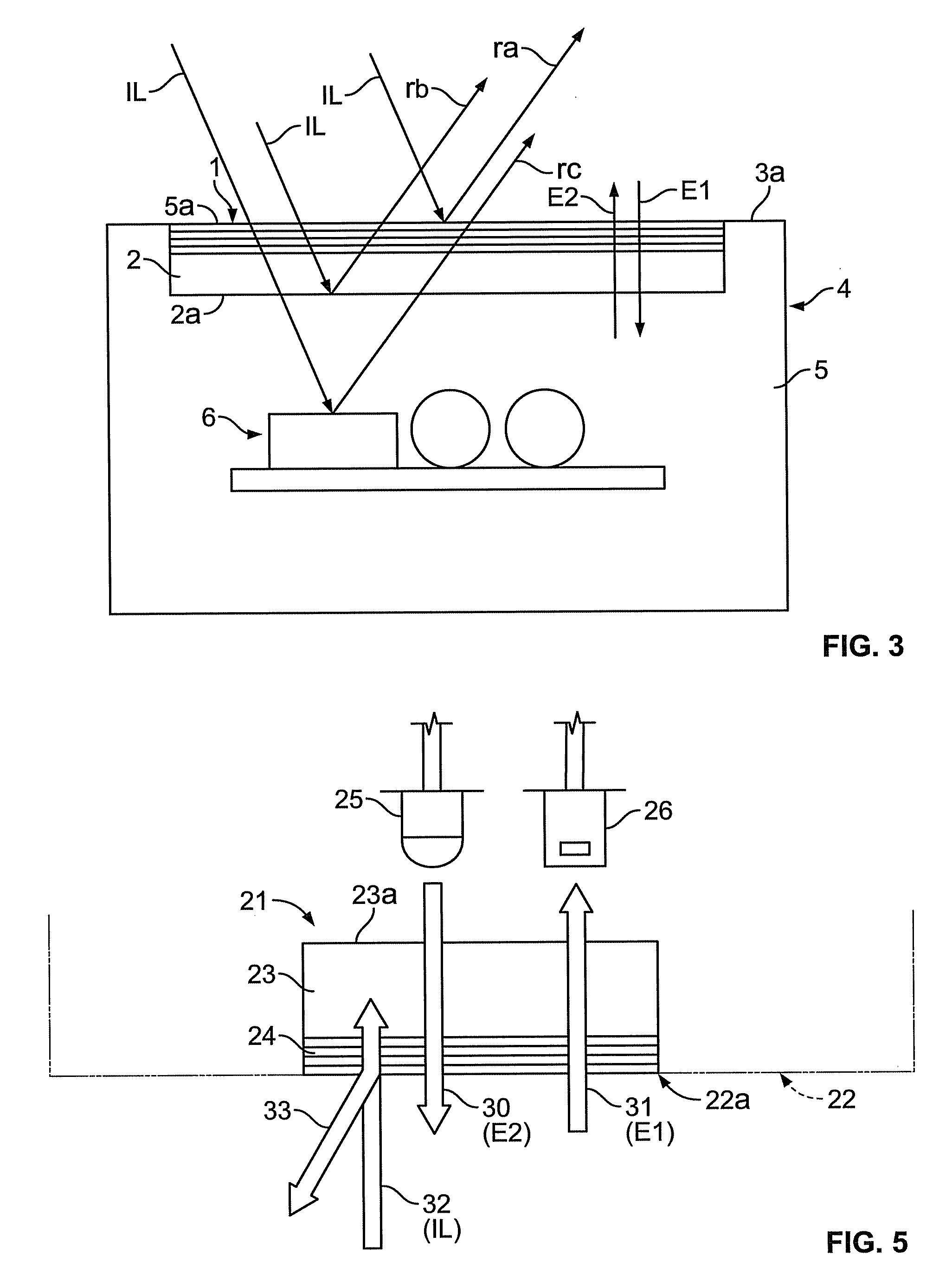
[0069]An infrared transparent cover 21 according to a first embodiment of the present invention will now be described with reference to FIG. 5.

[0070]A portable information terminal 22 serving as the electronic device includes a transceiver for transferring information or exchanging information in a cable-less manner with other electronic devices using infrared signals (e.g., infrared light having a wavelength in the vicinity of 850 nm). The infrared communication is performed in compliance with, for example, the IrDA standard. The cover 21 closes an opening (infrared signal port) 22a formed in the housing of the portable information terminal 22. The lower side as viewed in FIG. 5 is the outer surface of the cover 21 and the layers, and the upper side is the inner surface of the cover 21 and the layers.

[0071]The cover 21 includes a base layer 23 having infrared transparency and a dielectric multilayer film 24, which is formed on the outer surface of the base layer 23 with infrared tr...

example 1

[0090]A cover of example 1 will now be described with reference to FIGS. 6 and 7, and tables 1 and 2.

[0091]The cover of example 1 has the same layer structure as the cover 21 shown in FIG. 5 and includes a base layer 23 made of acrylic resin and a dielectric multilayer film 24 that transmits infrared light and reflect blue light. The dielectric multilayer film 24 is configured from eight layers of thin films in which film substance (ZrO2) of a material having high refraction index and film substance (SiO2) of a material having low refraction index are laminated in an alternate manner. The dielectric multilayer film 24 reflects light having a median wavelength ?c. The median wavelength ?c is related to the color of the reflected light, that is, the color of the cover. The eight layers forming the dielectric multilayer film 24 of example 1 are designed to reflect light having the median wavelength ?c of 495 nm, that is, blue light.

TABLE 1Example 1: blue color reflection, median wavele...

example 2

[0098]The cover of example 2 has the same layer structure as the cover 21 shown in FIG. 5 and includes a base layer 23 made of acrylic resin and a dielectric multilayer film 24 that reflects yellow light. The dielectric multilayer film 24 includes seven layers of thin films in which a film substance (ZrO2) for a material having high refraction index and a film substance (SiO2) for a material having low refraction index are laminated in an alternate manner. The median wavelength ?c of the dielectric multilayer film 24 is the wavelength (600 nm) of yellow reflected light.

TABLE 3Example 2: yellow color reflection, median wavelength ?c:600 nm, number of dielectric multilayer films: 7Air SidePhysical FilmOptical FilmThin Film LayerMaterialThickness (nm)Thickness n?d1SiO245.210.442ZrO274.9413SiO2101.9114ZrO274.9415SiO2102.9616ZrO284.391.1847SiO2192.061.864Base Layer 23Side

[0099]FIG. 8 shows the spectral reflectance characteristic and the spectral transmission characteristic of the dielect...


PUM


Abstract

Disclosed is an infrared-transmitting cover (21) comprising an infrared-transmitting base layer (23) and an infrared-transmitting dielectric multilayer film (24) which is arranged on the base layer (23). The infrared-transmitting cover (21) has optical characteristics since the dielectric multilayer film (24) selectively reflects visible light in a specific wavelength range, and the cover appears in the color corresponding to the specific wavelength range. A cover according to one embodiment of the present invention appears in a color other than black, namely such as blue, yellow or green, thereby enabling to improve decoration ability of infrared signal ports of electronic devices such as portable information terminals.

Description

TECHNICAL FIELD[0001]The present invention relates to infrared transparent covers, for example, a highly aesthetic infrared transparent cover attached to an infrared signal port for inputting and outputting infrared signals.BACKGROUND ART[0002]Infrared signals are used for short-distance wireless data transmission (e.g., IrDA standard) between electronic devices. Infrared signals are also used for remote operations performed to turn on and off or control the volume of home electric appliances such as TVs and VCRs.[0003]An infrared signal is received by an infrared light receiving element arranged in a receiver or a transmitter. Generally, the infrared light receiving element detects visible light in addition to infrared signals. In order to prevent ambient light such as visible light from entering the light receiving element, a black or dark colored resin window plate having near-infrared transparency is attached to an infrared signal port of a receiver or transmitter in the prior a...

Claims


Application Information

Patent Timeline
Patent Type & Authority Applications(United States)
IPC IPC(8): G02B5/26G02B5/28H01L31/02H01L31/12
CPCG02B5/281H01L33/44G02B5/26G02B5/28H01L31/02
Inventor HASHIGUCHI, TAKASHIMIYAGUCHI, AKIRA
Owner TOKAI OPTICAL CO LTD
Why Eureka
Try Eureka