LED reflector lamp

a technology of reflector lamps and reflectors, which is applied in the direction of transportation and packaging, semiconductor devices of light sources, lighting and heating apparatus, etc., can solve the problems of increasing the cost of manufacture and repair, emitted light is either not reflected at all or in undesirable ways, and the light is wasted insignificantly, so as to maximize the projected lumens

Active Publication Date: 2009-01-01
KOESTER GEORGE H
View PDF10 Cites 73 Cited by
  • Summary
  • Abstract
  • Description
  • Claims
  • Application Information

AI Technical Summary

Benefits of technology

[0008]In general, the invention is a reflective lamp comprising a reflective surface of chosen configuration, typically a parabolic configuration, and one or more light emitting diodes (LED's) as the illuminating source. The LED's are mounted on one or more occluding faces of a pedestal member that extends into the interior of the reflective surface. The occluding faces are disposed at an acute angle from the central axis with the faces either parallel to the axis or rearward inclined toward the interior of the reflective surface. Each face defines the maximum area or angle of dispersion of the light from the LED, such that for a given face having a planar surface light from an LED is emitted at most over a hemispherical area and will be reflected by only a portion of the reflector surface, thereby maximizing the projected lumens and particularly defining the direction and shape light beam projected from the lamp.

Problems solved by technology

One shortcoming of these typical reflector lamps is that a significant portion of the light emitted from the illumination source is wasted, since only a portion of the emitted light falls on the desired area of the reflective surface.
The remainder of the emitted light is either not reflected at all or is reflected in an undesirable manner outside of the desired light beam pattern.
Another shortcoming is that an optical refractive lens is required for many applications, which raises the cost of manufacture and the expense of repair should the lens be damaged.

Method used


Image

  • LED reflector lamp
  • LED reflector lamp
  • LED reflector lamp

Examples


Embodiment Construction

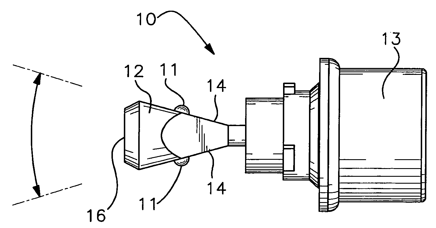
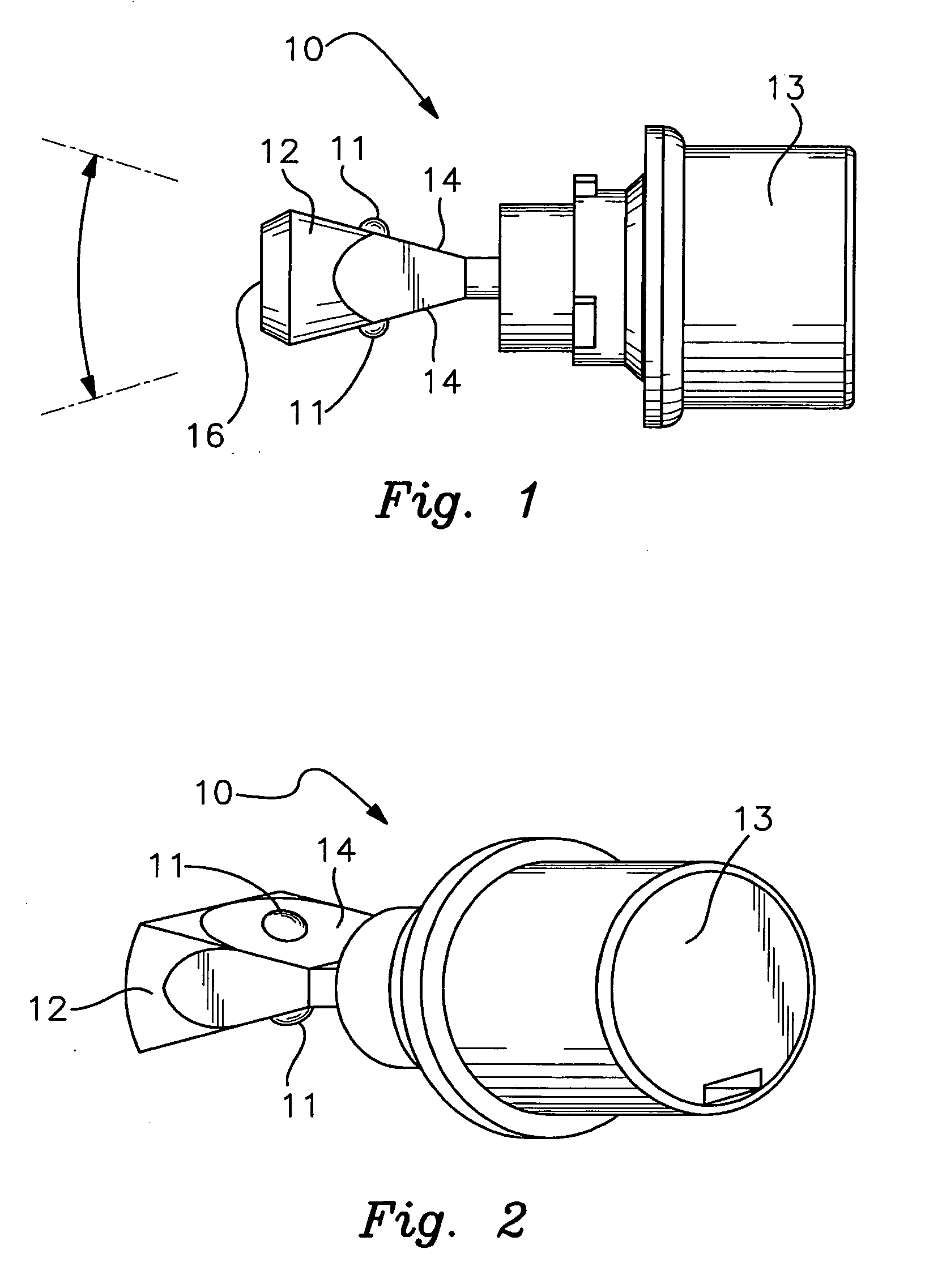
[0023]With reference to the drawings, the invention will now be described in detail with regard for the best mode and preferred embodiments. In a most general sense, the invention is a reflector lamp using one or more light emitting diodes (LED's) as illumination sources.

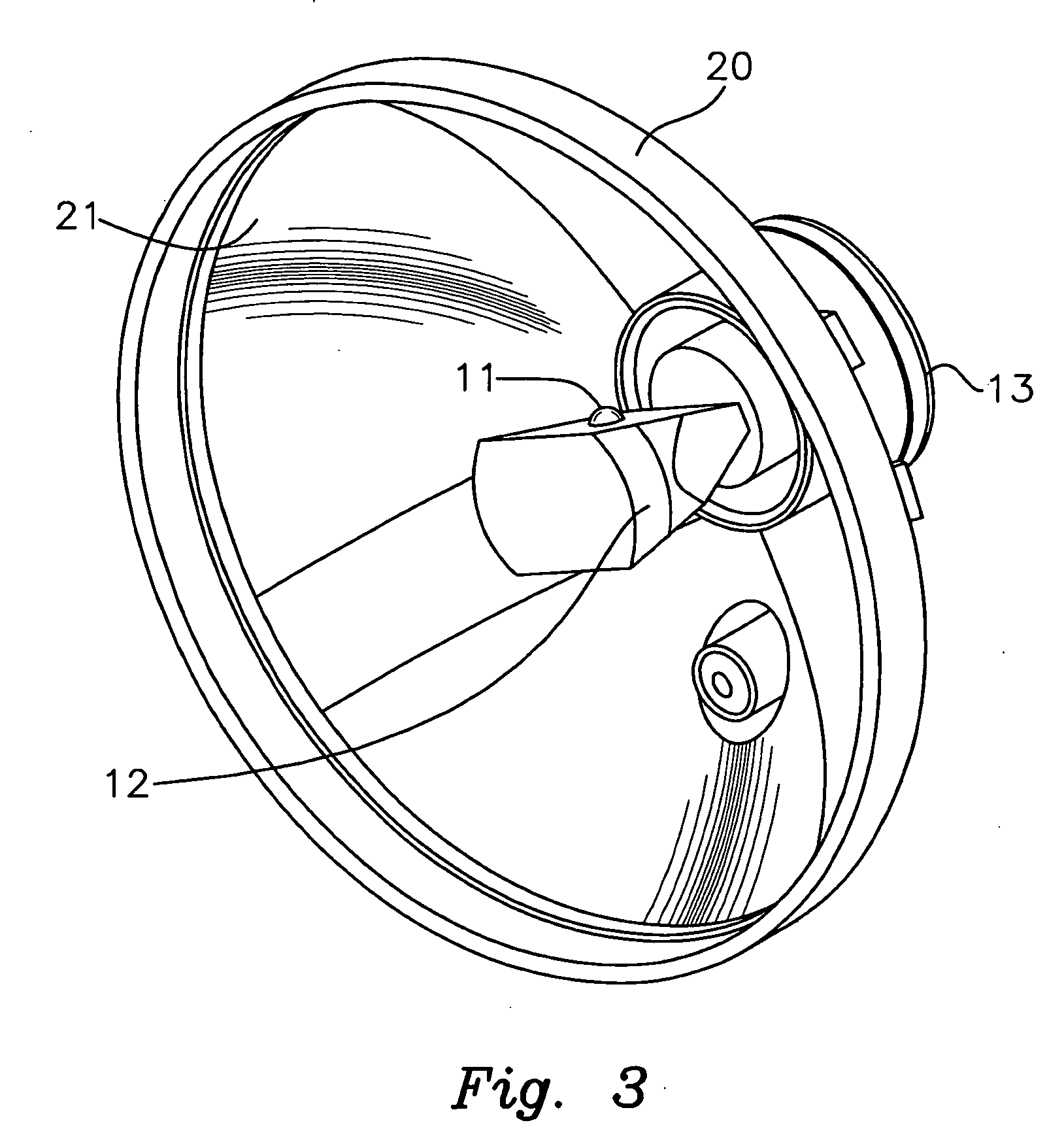
[0024]As shown in FIGS. 1 through 3, the LED reflector lamp comprises an assembly of operational components 10 mounted within a lamp housing 20. The lamp housing 20 comprises an internally disposed reflective surface 21, typically composed of a polished aluminum or similar light reflective material. The reflective surface 21 is configured so as to capture light from an LED illumination source 11 and project it from the lamp housing 20 in a controlled direction and pattern or shape. The reflective surface 21 as illustrated is shown as having a parabolic configuration, but it is contemplated that other shapes, such as for example and not limited to elliptical, segmented, polygonal, etc., may be utilized for specific a...


PUM


Abstract

A lamp having a reflective surface, a pedestal positioned within the interior defined by the reflective surface, and one or more light emitting diodes (LED's) mounted onto one or more occluding faces on the pedestal, such that each occluding face blocks light emitted from the LED's from a portion of the reflective surface. The occluding faces are oriented parallel to or at an acute angle to the central axis of the reflective surface.

Description

[0001]This application claims the benefit of U.S. Provisional Patent Application Ser. No. 60 / 932,434, filed May 31, 2007, the disclosure of which is incorporated herein by reference.BACKGROUND OF THE INVENTION[0002]This invention relates generally to the field of reflector lamps and more particularly to the field of reflector lamps comprising one or more light emitting diodes (LED) as the illumination source. Even more particularly, this invention relates to any such LED reflector lamps that project one or more controlled, directional light beams or patterns.[0003]Reflector lamps comprising an illumination source and a reflective surface are well known, and are found in such devices as flashlights, spotlights, automobile headlights or the like. Various illumination sources may be used, such as for example an incandescent filament bulb, a high intensity discharge lamp, a florescent lamp or an LED. A shaped reflective surface surrounds the illumination source and directs the light pho...

Claims


Application Information

Patent Timeline
Patent Type & Authority Applications(United States)
IPC IPC(8): F21V29/00F21V7/00
CPCF21K9/00F21S48/10F21S48/328F21S48/335F21V13/10F21V29/004F21V29/77F21W2101/06F21Y2101/02F21Y2111/007F21V29/71F21V29/763F21W2101/02F21Y2115/10F21Y2107/40F21K9/68F21S41/00F21S41/143F21S41/147F21S45/47F21S45/60F21W2107/10F21W2107/30F21S41/151
Inventor KOESTER, GEORGE H.
Owner KOESTER GEORGE H
Why Eureka
Try Eureka