

Keypad with tactile touch glass
a technology of tactile feedback and keypad, which is applied in the field of input devices, can solve problems such as insufficient tactile feedback solutions
- Summary
- Abstract
- Description
- Claims
- Application Information
AI Technical Summary
Benefits of technology
Problems solved by technology
Method used
Image

Examples
Embodiment Construction
[0029]The following detailed description of the invention refers to the accompanying drawings. The same reference numbers in different drawings may identify the same or similar elements. Also, the following detailed description does not limit the embodiments.
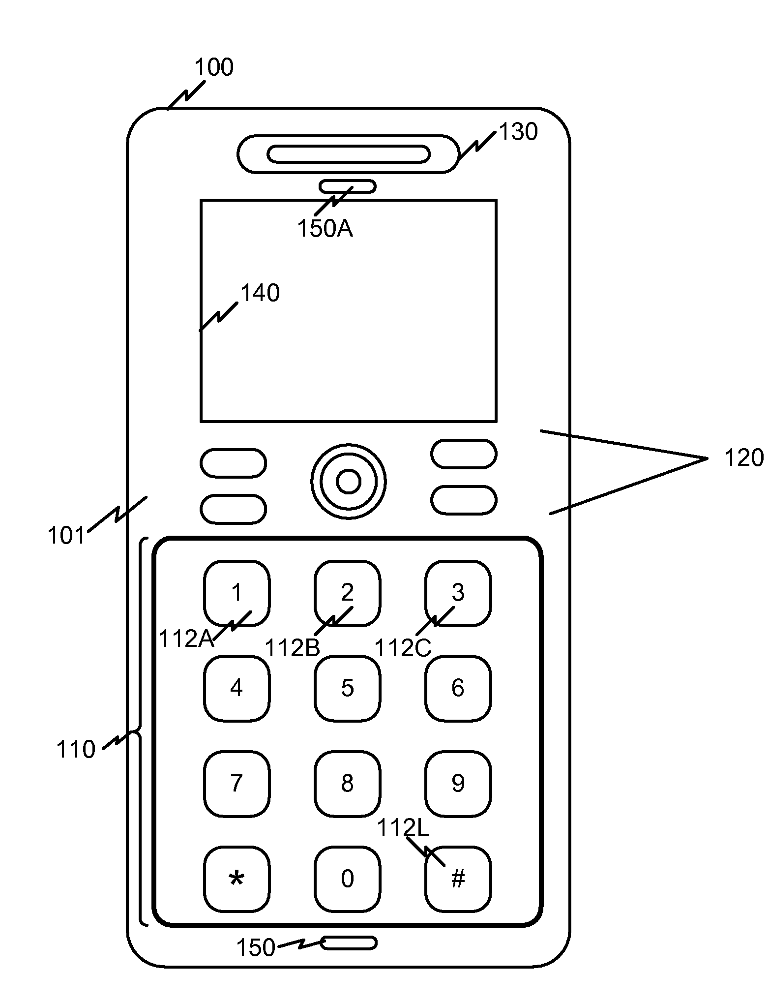
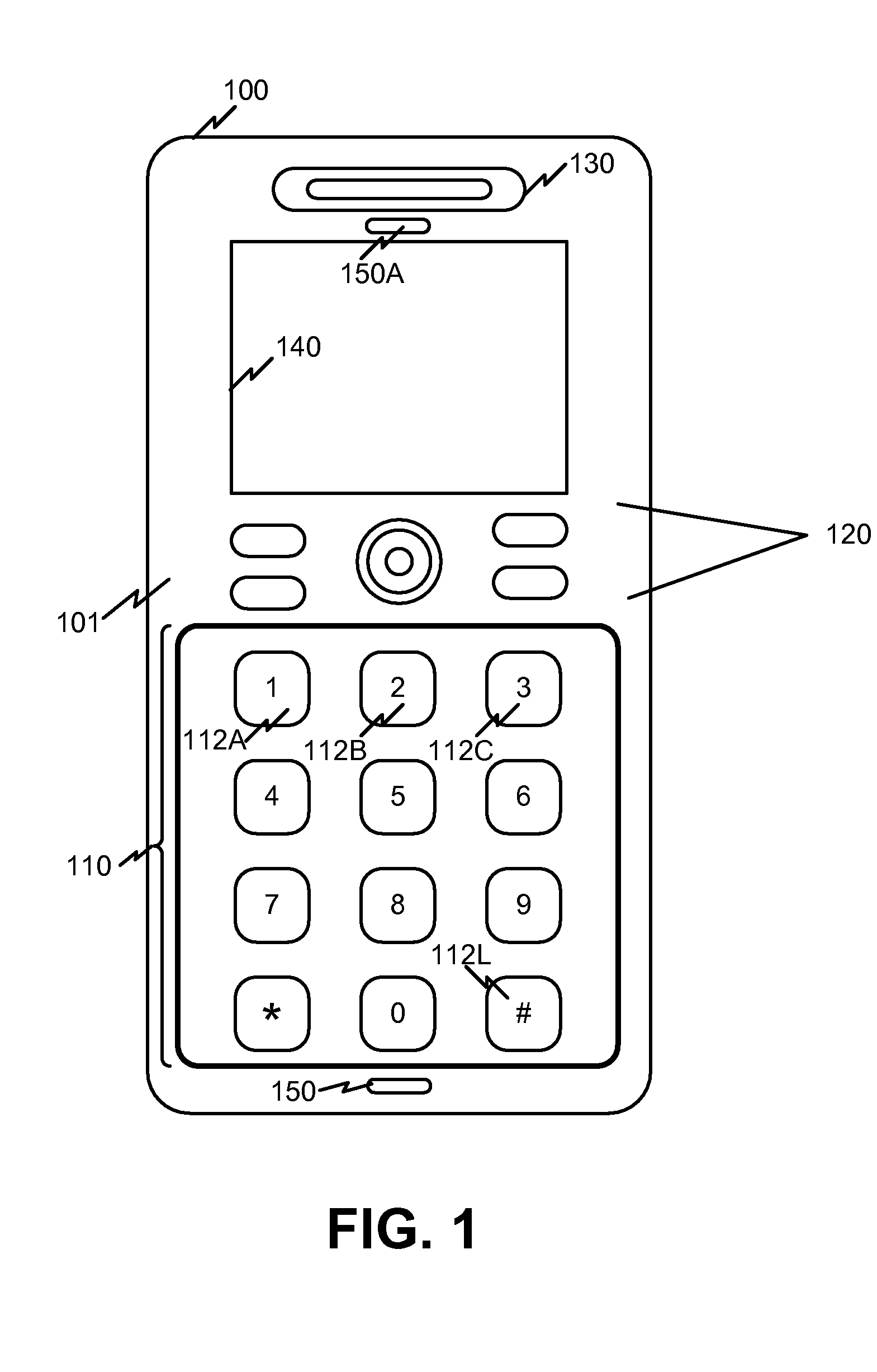
[0030]Exemplary implementations of the embodiments will be described in the context of a mobile communications terminal. It should be understood that a mobile communication terminal is an example of a device that can employ a keypad consistent with the principles of the embodiments and should not be construed as limiting the types or sizes of devices or applications that can use implementations of keypads described herein. For example, keypads consistent with the principles of the embodiments may be used on desktop communication devices, household appliances, such as microwave ovens and / or appliance remote controls, automobile radio faceplates, industrial devices, such as testing equipment, etc.
[0031]FIG. 1 is a diagram of an ex...
PUM
 Abstract
Description
Claims
Application Information