
Image processing system and method

a technology of image processing and image processing equipment, applied in the field of image processing apparatus and image processing method, can solve problems such as unsatisfactory display images

Inactive Publication Date: 2009-01-08
NISSAN MOTOR CO LTD
View PDF3 Cites 37 Cited by
  • Summary
  • Abstract
  • Description
  • Claims
  • Application Information

AI Technical Summary

Problems solved by technology

Thus, if the captured images are combined without adjustment, the resulting display image may be unsatisfactory.

Method used


Image

  • Image processing system and method
  • Image processing system and method
  • Image processing system and method

Examples


Embodiment Construction

[0016]In the above-described system of Japanese Unexamined Patent Application Publication No. 2007-72750, the brightness values of the captured images are automatically controlled by the AGC function of the vehicle mounted cameras. However, differences in the magnitude of luminance level correction provided by the individual vehicle mounted cameras may increase the required magnitude of luminance value correction. Furthermore, temporarily compressed luminance values may not be sufficiently decompressed after the correction, resulting in the display image being partially blurred. In contrast, embodiments of the invention are capable of providing good continuity of a display image, thereby generating a satisfactory display image without any visibly discomforting areas in the entire image.

[0017]Certain embodiments of the invention are described in detail below with reference to the drawings. Herein, the invention is described in connection with a downward image display system that capt...


PUM


Abstract

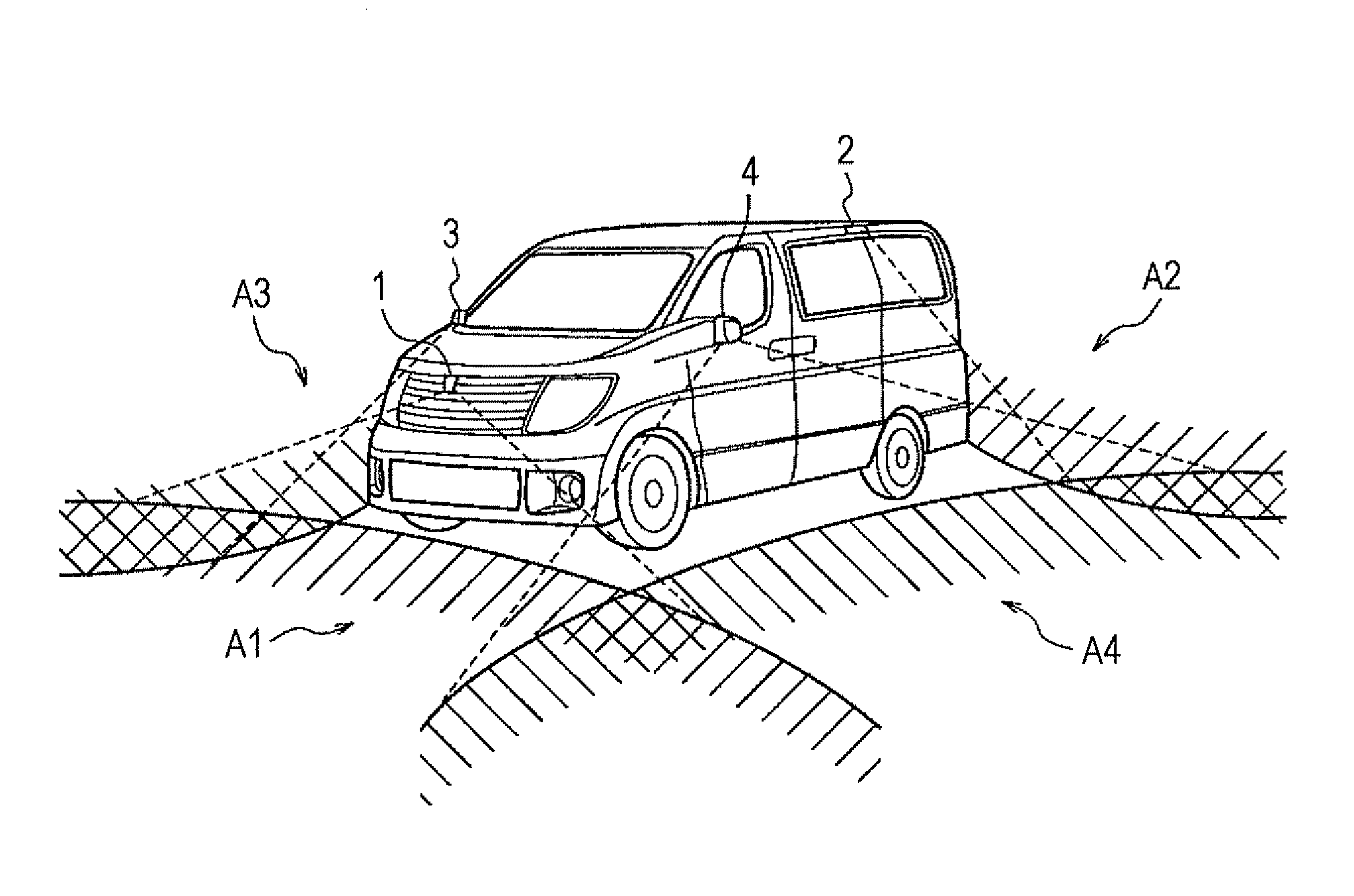
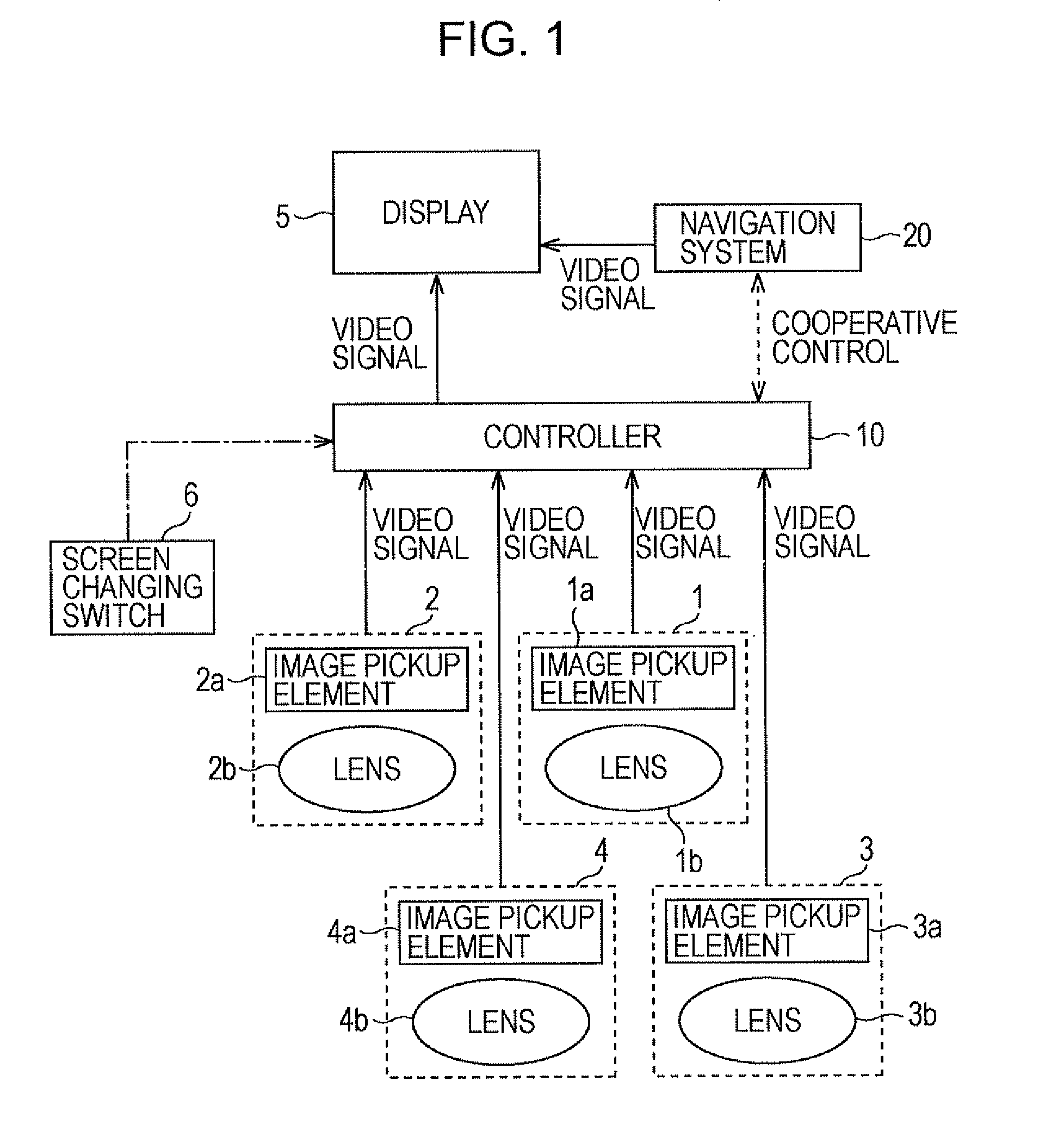
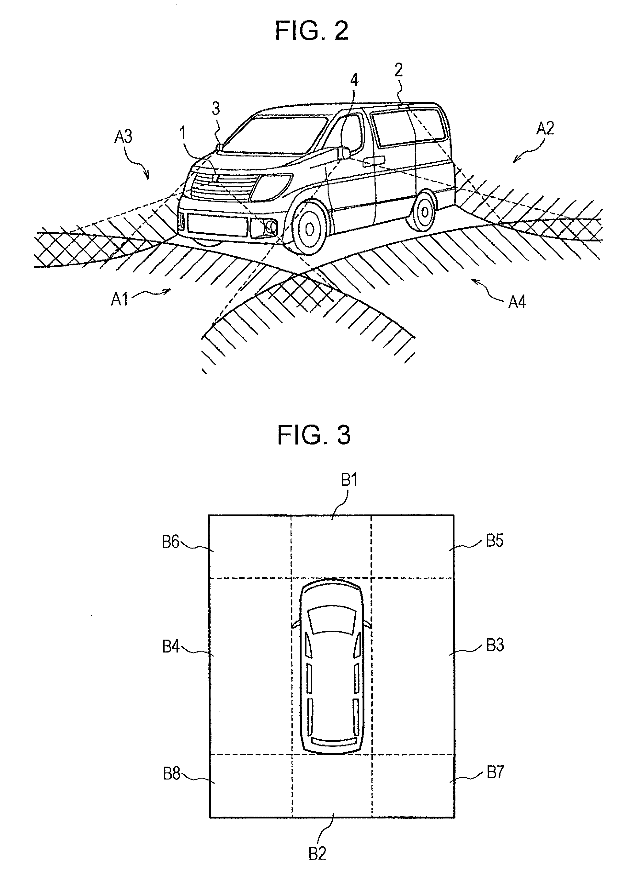
An image processing system for a vehicle including a plurality of image pickup devices directed toward different predetermined areas around the vehicle to provide captured images and a display unit. Subject areas are extracted from the captured images, wherein the subject areas correspond to partial areas of predetermined areas captured by the image pickup devices that are adjacent to the image pickup devices. Brightness values of the subject areas are equalized to provide processed images, and the processed image are combined to generate a display image.

Description

CROSS-REFERENCE TO RELATED APPLICATIONS[0001]This application claims priority from Japanese Patent Application Serial No. 2007-174208, filed Jul. 2, 2007, which is incorporated herein in its entirety by reference.TECHNICAL FIELD[0002]The present invention relates to an image processing apparatus and an image processing method that combines images captured with a plurality of cameras to generate a single continuous display image.BACKGROUND[0003]Image processing systems where a plurality of images are captured by a plurality of vehicle mounted cameras, and the captured images are combined to generate a single display image are known. The single display image is displayed on, for example, a display screen used for navigation. However, the captured images may have different average luminance values in accordance with the mounting positions, directions and characteristics of the vehicle mounted cameras. Thus, if the captured images are combined without adjustment, the resulting display i...

Claims


Application Information

Patent Timeline
IPC IPC(8): H04N7/18
CPCB60R1/00B60R1/12B60R2001/1253B60R2300/102B60R2300/303B60R2300/607H04N7/181G06T3/4038G06T2207/30252H04N5/23238H04N5/247H04N5/3572B60R2300/802H04N23/60H04N23/698H04N25/61H04N23/90B60R1/27
Inventor KANAOKA, AKIHIROSAKAI, KAZUHIKOSUGAWARA, DAISUKEOTANI, SOTARO
Owner NISSAN MOTOR CO LTD
Learn More