Drive and Braking Force Control Device for Vehicle
a technology of braking force and control device, which is applied in the direction of braking system, instruments, analogue processes for specific applications, etc., can solve the problem of limit the braking/driving force that can be generated by each wheel
- Summary
- Abstract
- Description
- Claims
- Application Information
AI Technical Summary
Benefits of technology
Problems solved by technology
Method used
Image

Examples
first embodiment
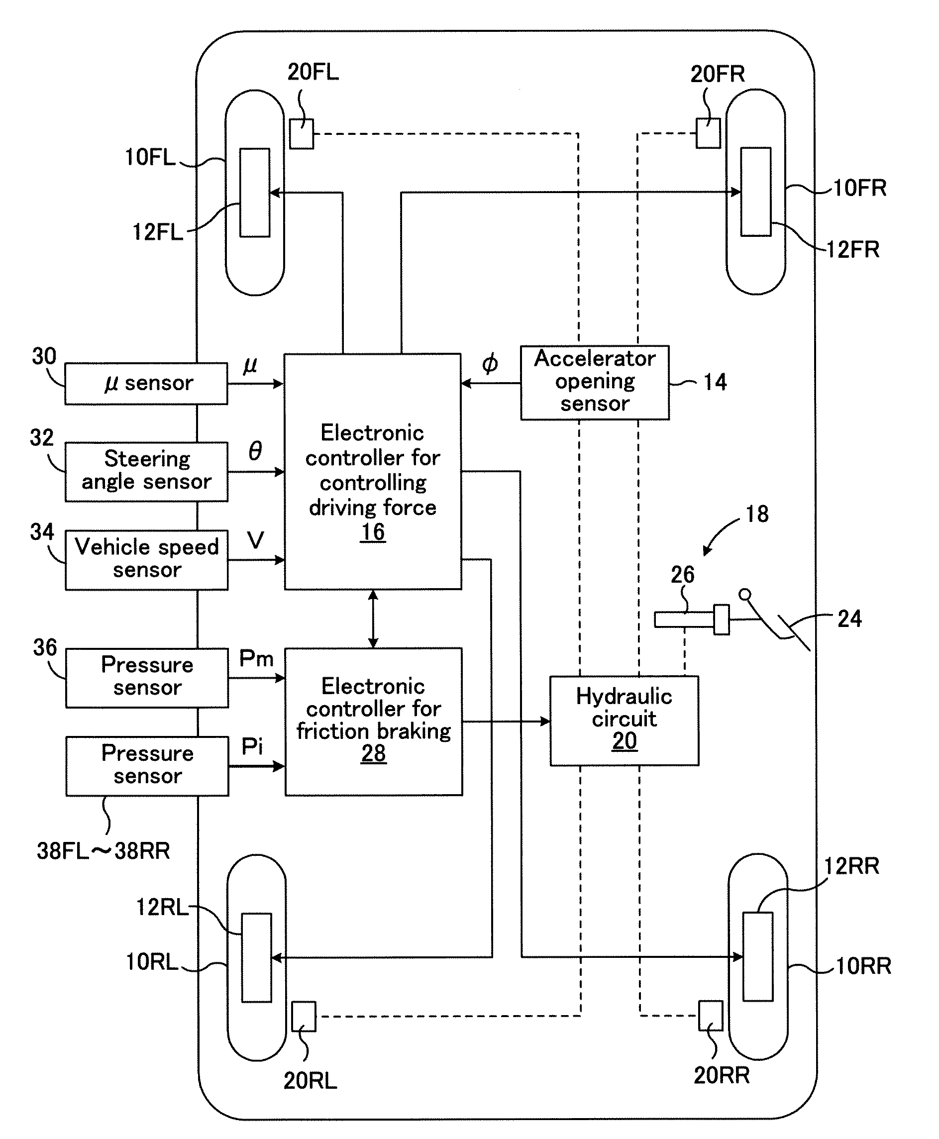
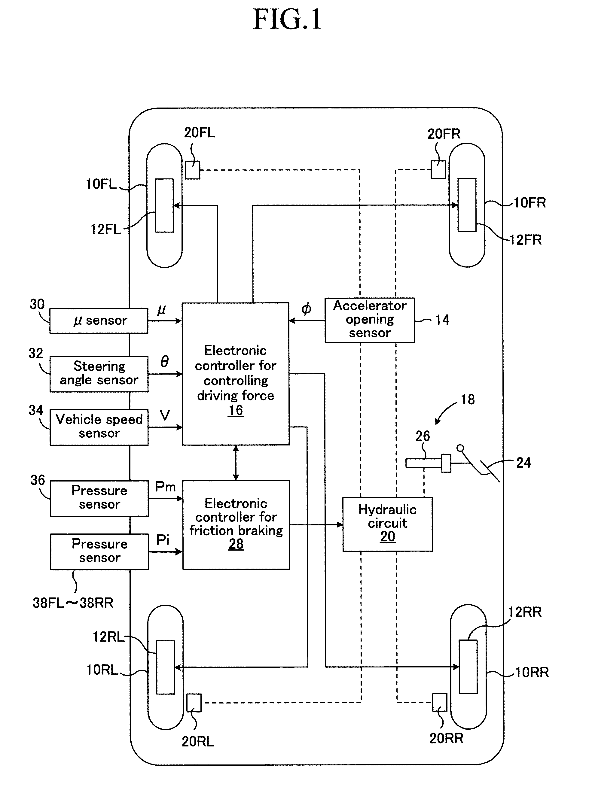
[0058]FIG. 1 is a schematic block diagram showing a braking / driving force control apparatus applied to a four-wheel-drive vehicle of a wheel-in-motor type according to a first embodiment of the present invention.
[0059]In FIG. 1, numerals 10FL and 10FR respectively represent left and right front wheels that are steering wheels, and numerals 10RL and 10RR respectively represent left and right rear wheels that are non-steering wheels. Electric motor generators 12FL and 12FR that are in-wheel motors are incorporated into the left and right front wheels 10FL and 10FR respectively, whereby the left and right front wheels 10FL and 10FR are driven by the electric motor generators 12FL and 12FR. The electric motor generators 12FL and 12FR also function as regenerative electric generators for each of the left and right front wheels upon the braking, so that they generate regenerative braking force.
[0060]Similarly, electric motor generators 12RL and 12RR that are in-wheel motors are incorporat...
second embodiment
[0108]FIG. 5 is a schematic block diagram showing a braking / driving force control apparatus applied to a four-wheel-drive vehicle in which driving force and regenerative braking force from a single electric motor generator, which is common to four wheels, are controlled so as to be distributed to front and rear wheels and right and left wheels according to a second embodiment of the present invention. The components in FIG. 5 same as those in FIG. 1 are identified by the same numerals in FIG. 1.
[0109]In this second embodiment, an electric motor generator 40 is provided that serves as a driving source common to the front left wheel 10FL, front right wheel 10FR, rear left wheel 10RL, and rear right wheel 10RR. The driving force or the regenerative braking force from the electric motor generator 40 is transmitted to a front-wheel propeller shaft 44 and rear-wheel propeller shaft 46 through a center differential 42 that can control the distribution ratio to the front wheels and rear whe...
third embodiment
[0153]FIG. 10 is a flowchart showing an main part of a braking / driving force control routine in a third embodiment of a vehicle braking / driving force control apparatus that is applied to a four-wheel-drive vehicle of a wheel-in-motor type and is made as an modified example of the first embodiment. Steps in FIG. 10 same as Steps shown in FIG. 3 are identified by the same numbers in FIG. 3.
[0154]In this third embodiment, it is determined at Step 80 whether or not the absolute value of the target braking / driving force Fvn is greater than a reference value Fvnc (a positive constant smaller than Fvdmax). When a positive determination is made, the program proceeds to Step 100, and when a negative determination is made, the program proceeds to Step 90.
[0155]At Step 100, it is determined whether or not the absolute value of the vehicle target braking / driving force Fvn is greater than the vehicle maximum braking force Fvbmax. When a negative determination is made, the program proceeds to Ste...
PUM
 Abstract
Description
Claims
Application Information