
Camera of an electronic device used as a proximity detector

Inactive Publication Date: 2009-01-15
SONY ERICSSON MOBILE COMM AB
View PDF12 Cites 36 Cited by
  • Summary
  • Abstract
  • Description
  • Claims
  • Application Information

AI Technical Summary

Benefits of technology

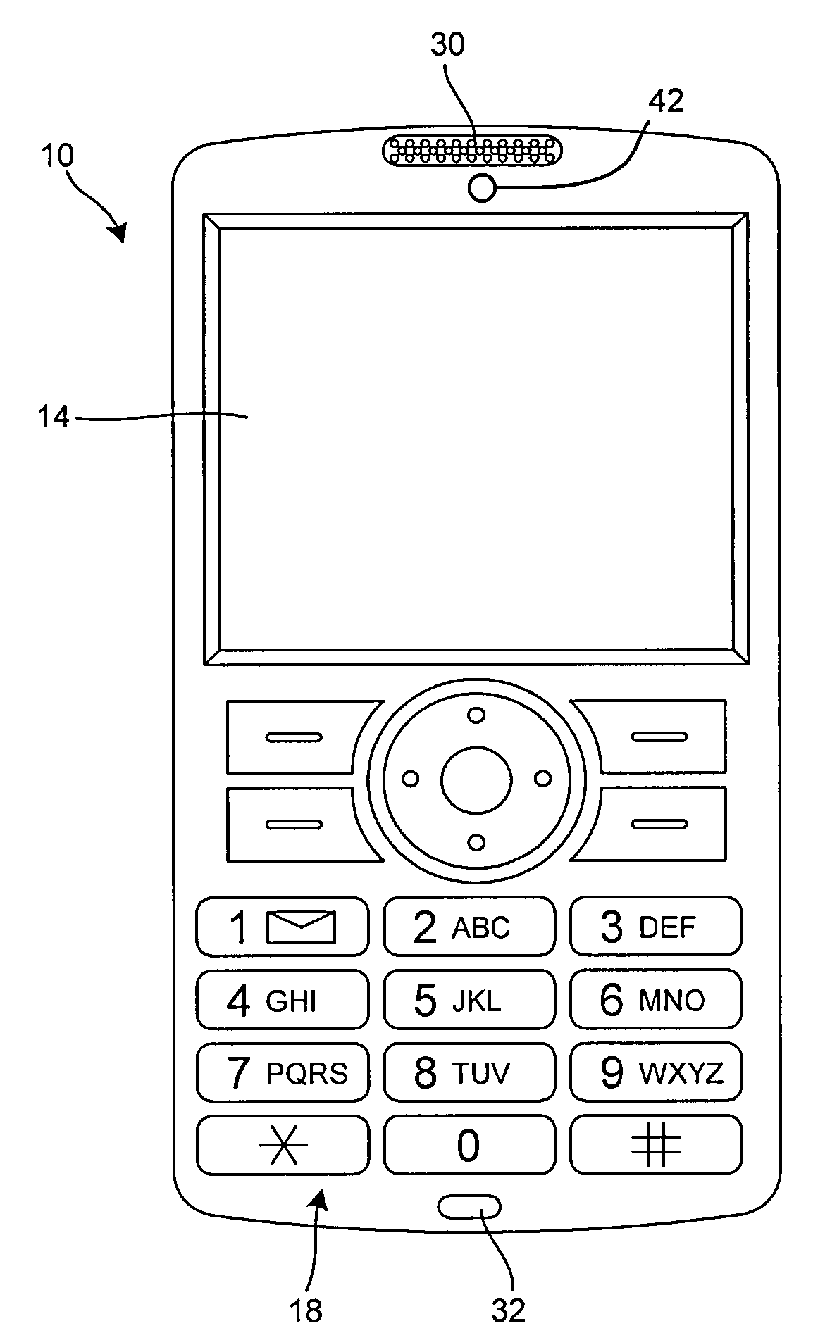
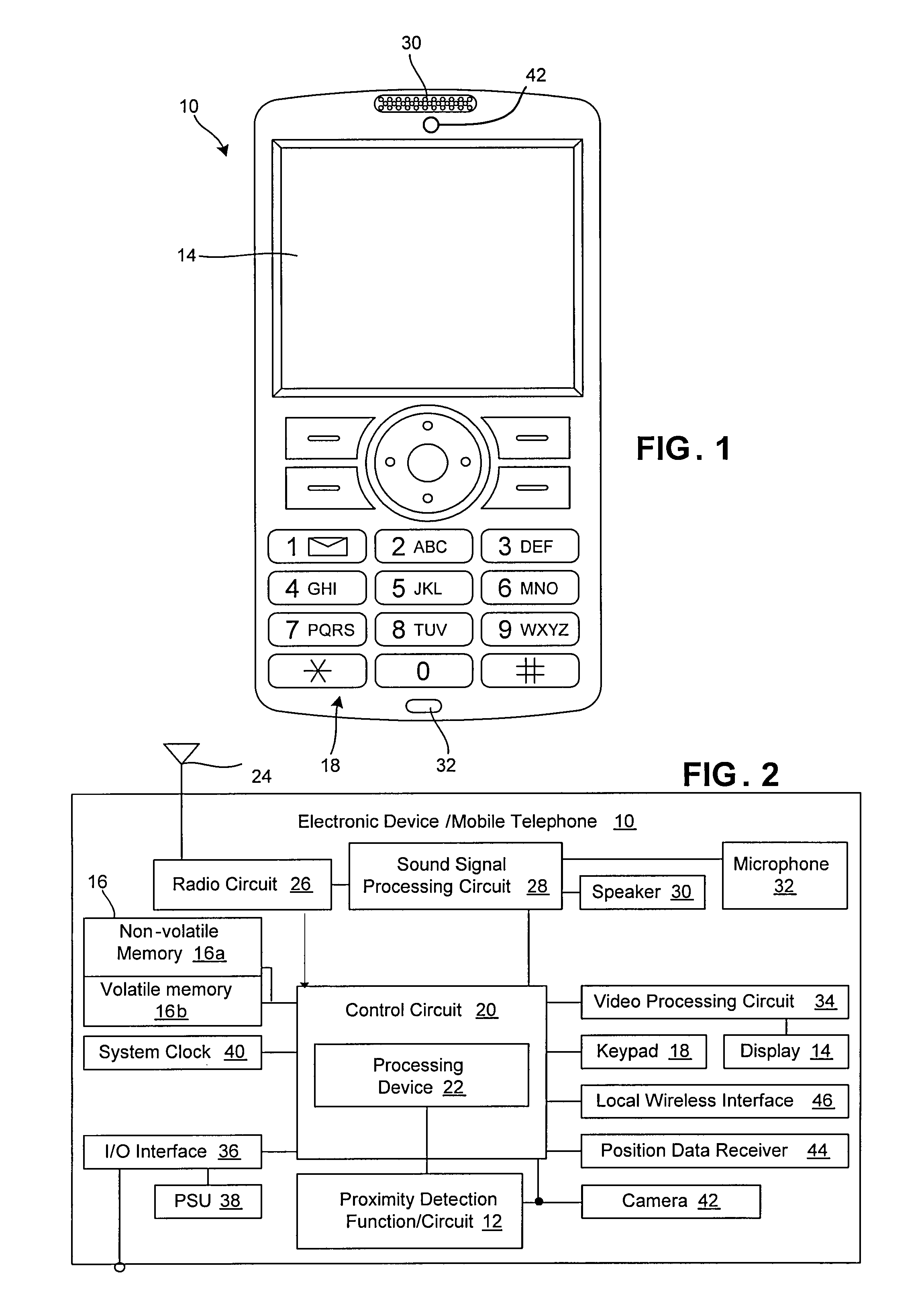
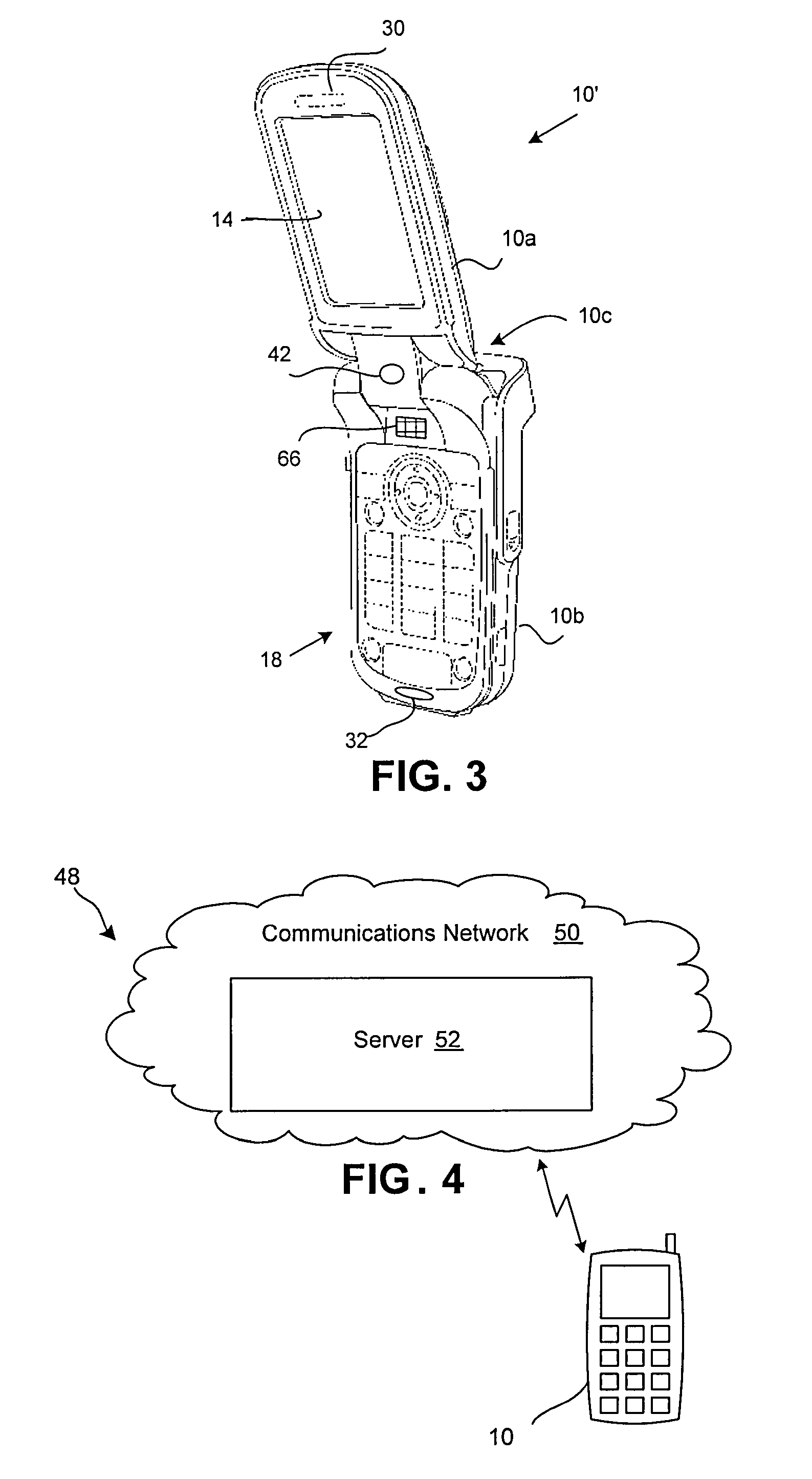
[0006]The present invention enables a commonly found feature of electronic devices, in addition to performing its primary function, to perform secondary functions commonly implemented via additional hardware. More particularly, an optical input function (e.g., a camera function) of the electronic device, for example, in addition to performing image functions such as obtaining snap shots and / or videos (e.g., movie clips and / or videos used during video phone calls), also may be used to detect a proximity of an object relative to the electronic device. Such proximity detection can include, for example, detection of the electronic device relative to a user of the device, an orientation of parts of the electronic device relative to each other (e.g., whether or not the electronic device open or closed), or a storage condition of the device (e.g., whether or not the device is placed within a carrying case). This information then can be used to control the operation of other features of the electronic device, such as a back light of a display, audio output signals and / or levels provided to speakers, etc. Moreover, proximity detection via optical input enables at least one additional component (e.g., a proximity switch) to be removed from the electronic device, thereby reducing cost and weight of the electronic device.

Problems solved by technology

The addition of hardware, however, requires physical space within the electronic device and, therefore, may contribute to an increase in size and weight of the electronic device.
The added hardware also increases the cost of the electronic device.
These demands, however, create a “catch-22”, wherein additional features implemented in the electronic device tend to increase the size and weight of the electronic device.
Conversely, decreasing the size and / or weight of the electronic device tends to limit the features (particularly features that require additional hardware) that may be implemented in the electronic device.

Method used


Image

  • Camera of an electronic device used as a proximity detector
  • Camera of an electronic device used as a proximity detector
  • Camera of an electronic device used as a proximity detector

Examples


Embodiment Construction

[0038]Embodiments of the present invention will now be described with reference to the drawings, wherein like reference numerals are used to refer to like elements throughout. It will be understood that the figures are not necessarily to scale.

[0039]The interchangeable terms “electronic equipment” and “electronic device” include portable radio communication equipment. The term “portable radio communication equipment,” which hereinafter is referred to as a “mobile radio terminal,” includes all equipment such as mobile telephones, pagers, communicators, electronic organizers, personal digital assistants (PDAs), smart phones, portable communication apparatus, portable gaming devices, portable media devices (video and / or audio), and the like.

[0040]In the present application, embodiments of the invention are described primarily in the context of a mobile telephone. However, it will be appreciated that the invention is not intended to be limited to the context of a mobile telephone and ma...


PUM


Abstract

A portable electronic device includes an optical input device operative to capture image data, at least one subsystem for controlling at least one operating parameter of the electronic device, and a proximity detection circuit operatively coupled to said optical input device and said subsystem. The proximity detection circuit is operative to determine if an object is within a predetermined distance of the electronic device based on the captured image data and, based on the determination, command the at least one subsystem to change the least one operating parameter.

Description

TECHNICAL FIELD OF THE INVENTION[0001]The present invention relates generally to electronic devices, such as electronic devices for engaging in voice communications. More particularly, the invention relates to a device and method for using a camera to simulate a proximity switch in electronic devices.DESCRIPTION OF THE RELATED ART[0002]Mobile and / or wireless items of electronic devices are becoming increasingly popular and are now in wide-spread use. In addition, the features associated with certain types of electronic devices have become increasingly diverse. To name a few examples, many electronic devices include cameras, text messaging capability, Internet browsing functionality, electronic mail capability, video playback capability, audio playback capability, image display capability, navigation capability, and hands-free headset interfaces.[0003]New features for electronic devices are constantly being developed and brought to market. Some of these new features may be implemente...

Claims


Application Information

Patent Timeline
IPC IPC(8): G08B21/00
CPCH04M1/0245H04M1/22H04M2250/52H04M2250/10H04M1/605
Inventor PALMQVIST, FREDRIKSCHACK, GORAN W.
Owner SONY ERICSSON MOBILE COMM AB
Learn More