Set For Creating An Offset-Resurfacing Hip-Joint Implant

a hip joint and implant technology, applied in the field of set for creating an offset resurfacing hip joint implant, can solve the problem of eccentricity in the outer shape, and achieve the effect of compensating the defective position of the hip joint head

Inactive Publication Date: 2009-01-15
ORTHODYNAMICS GMBH
View PDF1 Cites 207 Cited by
  • Summary
  • Abstract
  • Description
  • Claims
  • Application Information

AI Technical Summary

Benefits of technology

[0012]An object of the present invention is now to improve the set mentioned above for creating a resurfacing hip-joint implant, in such a way that defective positions of the hip-joint head can be compensated.

Problems solved by technology

However, its wall in the region of the base edge increases constantly viewed in cross section from a thickness of 2 mm to 6 mm, so that an eccentricity arises in its outer shape.

Method used


Image

  • Set For Creating An Offset-Resurfacing Hip-Joint Implant
  • Set For Creating An Offset-Resurfacing Hip-Joint Implant
  • Set For Creating An Offset-Resurfacing Hip-Joint Implant

Examples


Embodiment Construction

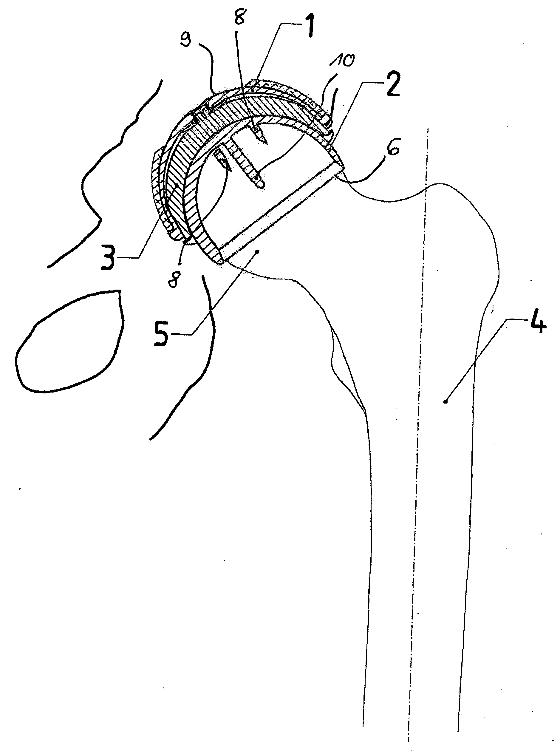
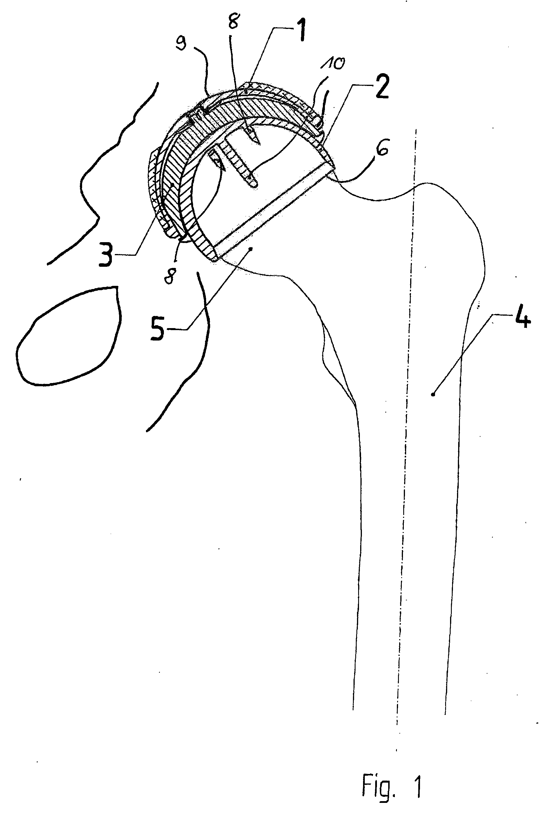
[0024]FIG. 1 illustrates schematically how the hip-joint implant, which has been created from a set according to an embodiment of the invention, is implanted. The metallic cap 2 is set on the hip-joint head 5 on the femur 4. The cap can be fixed there by a thin cement film in the interior of the cap.

[0025]The metallic shell 1 is set in the natural acetabulum 9 and fixed there with a thin cement film. The cement that is used has a very low viscosity.

[0026]The inlay 3, which forms the sliding partner for the metallic cap 2, is set in the shell 1. In the interior of the hip-joint head cap 2, a guiding peg 10, which engages in a borehole to be formed in the femoral neck 5, is formed proximally and in the exact center in the pole region. In addition, in the interior of the hip-joint head cap 2, at least two anti-rotation elements 8 project into the cap interior. The anti-rotation elements ensure that the position of the cap 2 set once on the joint head 5 is maintained stably over a long ...


PUM


Abstract

A set is provided for creating an offset-resurfacing hip-joint implant. The set includes a 1 to 1.5 mm thick metallic acetabulum shell (1) for insertion into the natural acetabulum, from which only cartilage has been removed, a metallic head cap (2) for placement on the natural hip-joint head, from which only cartilage has been removed, and an inlay (3) for insertion into the acetabulum shell (1) as a sliding partner for the head cap (2). The inlay has a material thickness of 2 to 5 mm. The head cap (2) has a wall thickness which increases constantly from a thickness of 2 mm to 6 mm viewed in cross section in the region of the base edge (6) of the head cap, so that an eccentricity is produced in its outer shape

Description

BACKGROUND OF THE INVENTION[0001]The invention relates to a set for creating an offset-resurfacing hip-joint implant. This is understood to be a surface replacement for the natural sliding or articulating surfaces of the acetabulum and the hip-joint head.[0002]So-called cap implants, which are placed over the prepared, natural remaining joint head and which can then be fixed in this position, are being used more and more in recent years. Cap implants comprise a cap, which has an outer shape patterned to the natural joint ball and which can be placed on a (partially) prepared, natural remaining joint head. Such an implant can be created from the so-called set for creating a reinforcement implant according to German Patent DE 102 18 801.[0003]A prerequisite for a stable secondary fixation is stable bone material of the remaining bone. For example, in the already mentioned patent it is proposed to couple a peg to the joint head cap, wherein this peg is set in a corresponding milled sec...

Claims


Application Information

Patent Timeline
Patent Type & Authority Applications(United States)
IPC IPC(8): A61F2/32
CPCA61F2/32A61F2310/00011A61F2/3603A61F2/4684A61F2002/30324A61F2002/30326A61F2002/3038A61F2002/30841A61F2002/30892A61F2002/3403A61F2002/3414A61F2002/3438A61F2002/4631A61F2220/0033A61F2250/0036A61F2250/0037A61F2/34A61F2002/30331A61F2002/30593
Inventor GRUNDEI, HANSGERDESMEYER, LUDGER
Owner ORTHODYNAMICS GMBH
Why Eureka
Try Eureka