True aim putter
a putter and true aim technology, applied in the field of putters, can solve the problems of lack of visual feedback during the stroke itself, lack of contrast, etc., and achieve the effects of improving visual feed back, good visual feedback of motion, and better detection of putting stroke errors
- Summary
- Abstract
- Description
- Claims
- Application Information
AI Technical Summary
Benefits of technology
Problems solved by technology
Method used
Image
Examples
first embodiment
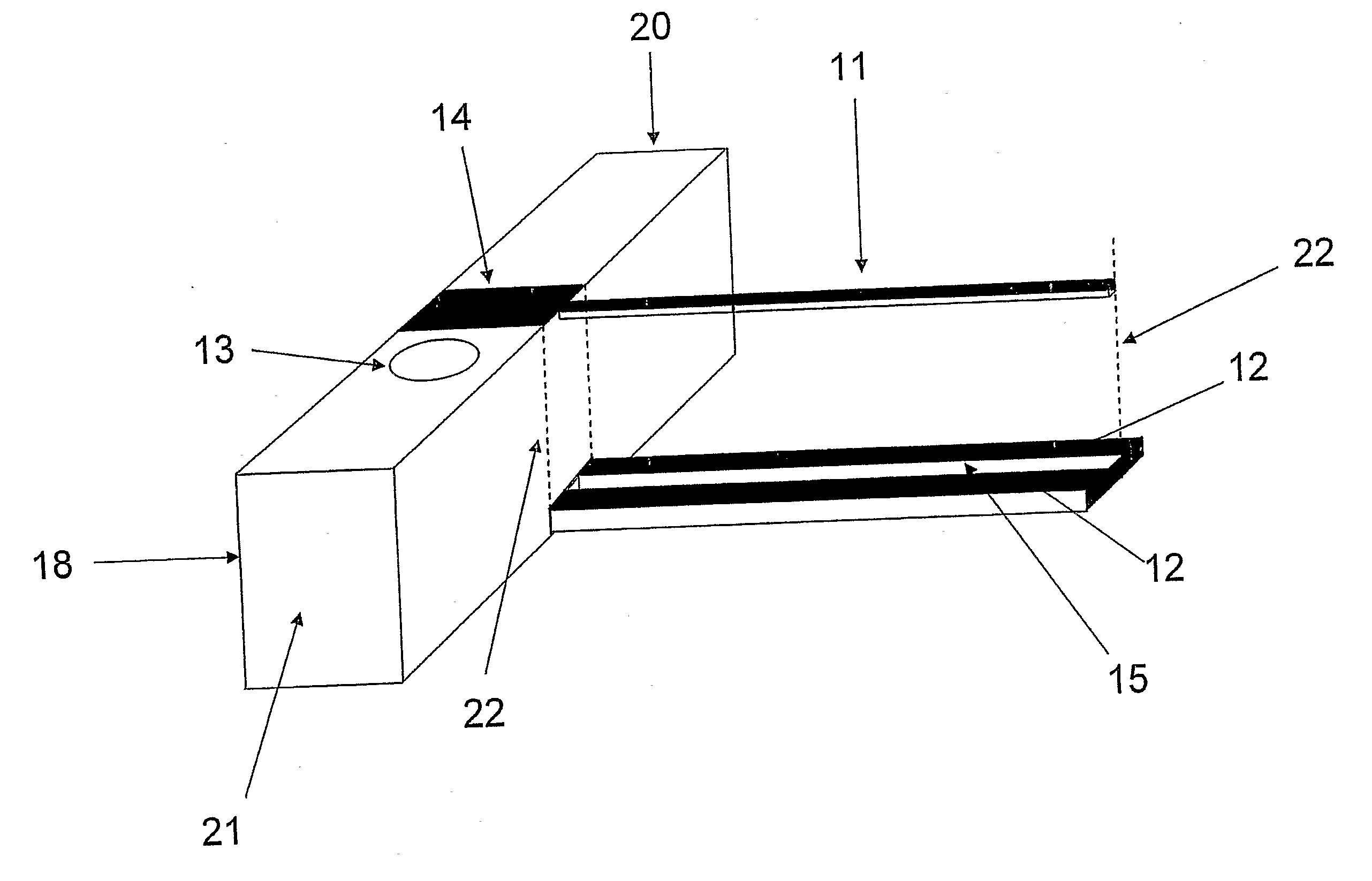
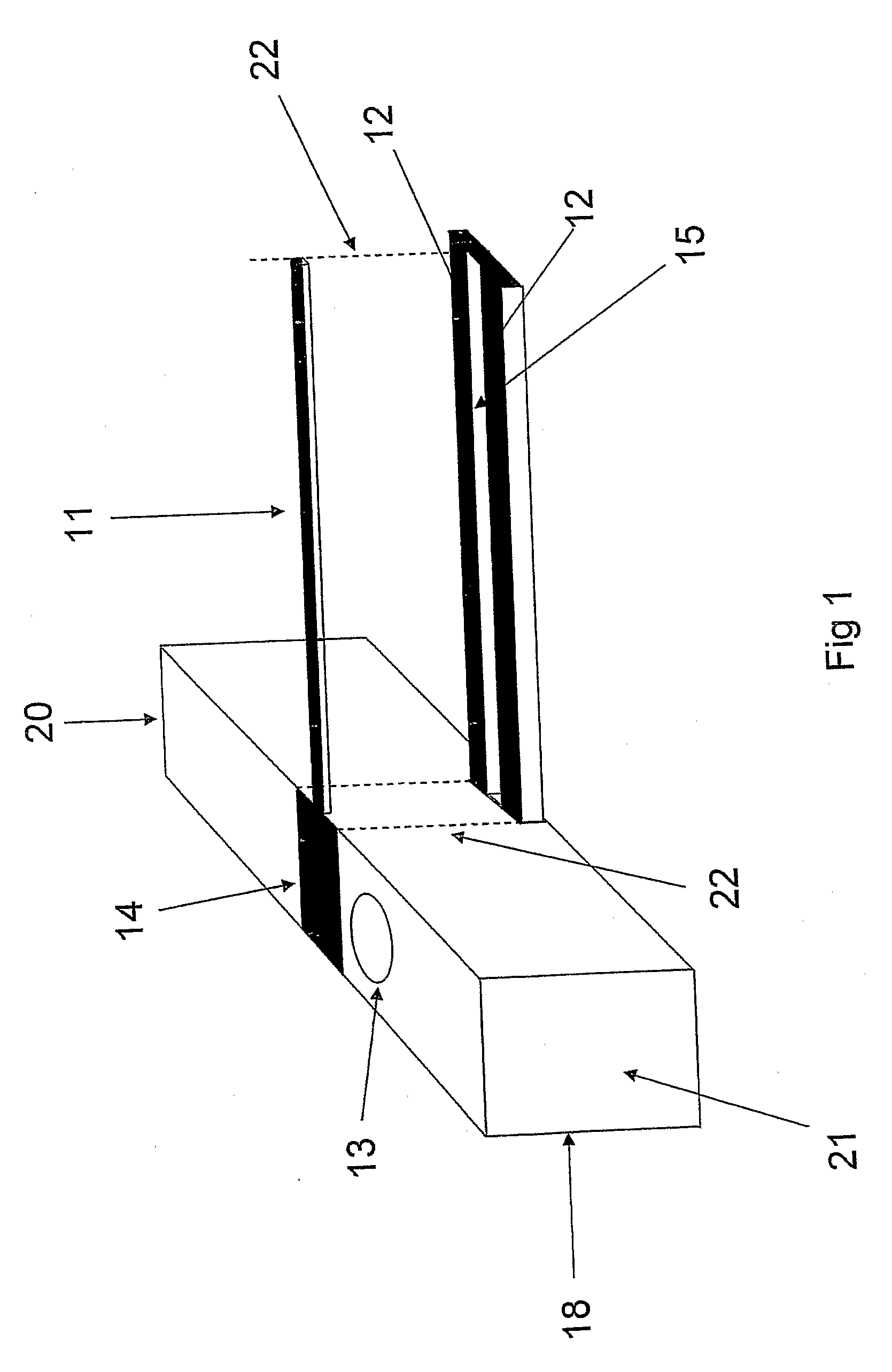
[0031]An alternate embodiment shown in FIG. 6 comprises two parallel indicator bars 33 located on the upper level, spaced apart from each other forming a slot 31, and two parallel warning strips 32 and 35 located on the lower level. Warning strips 32 and 35 are spaced apart from each other defining an elongated strip 34. Elongated strip 34 has approximately the same width as slot 31. As in the first embodiment, the width of indicator bars 33, warning strips 32 and 35 and elongated strip 34 are all approximately equal, and the indicator strips and warning strips are in vertical alignment with each other. As shown in FIG. 9A, the width of rectangular marking 14 is approximately equal to the distance between the outside edges of indicator bars 33.
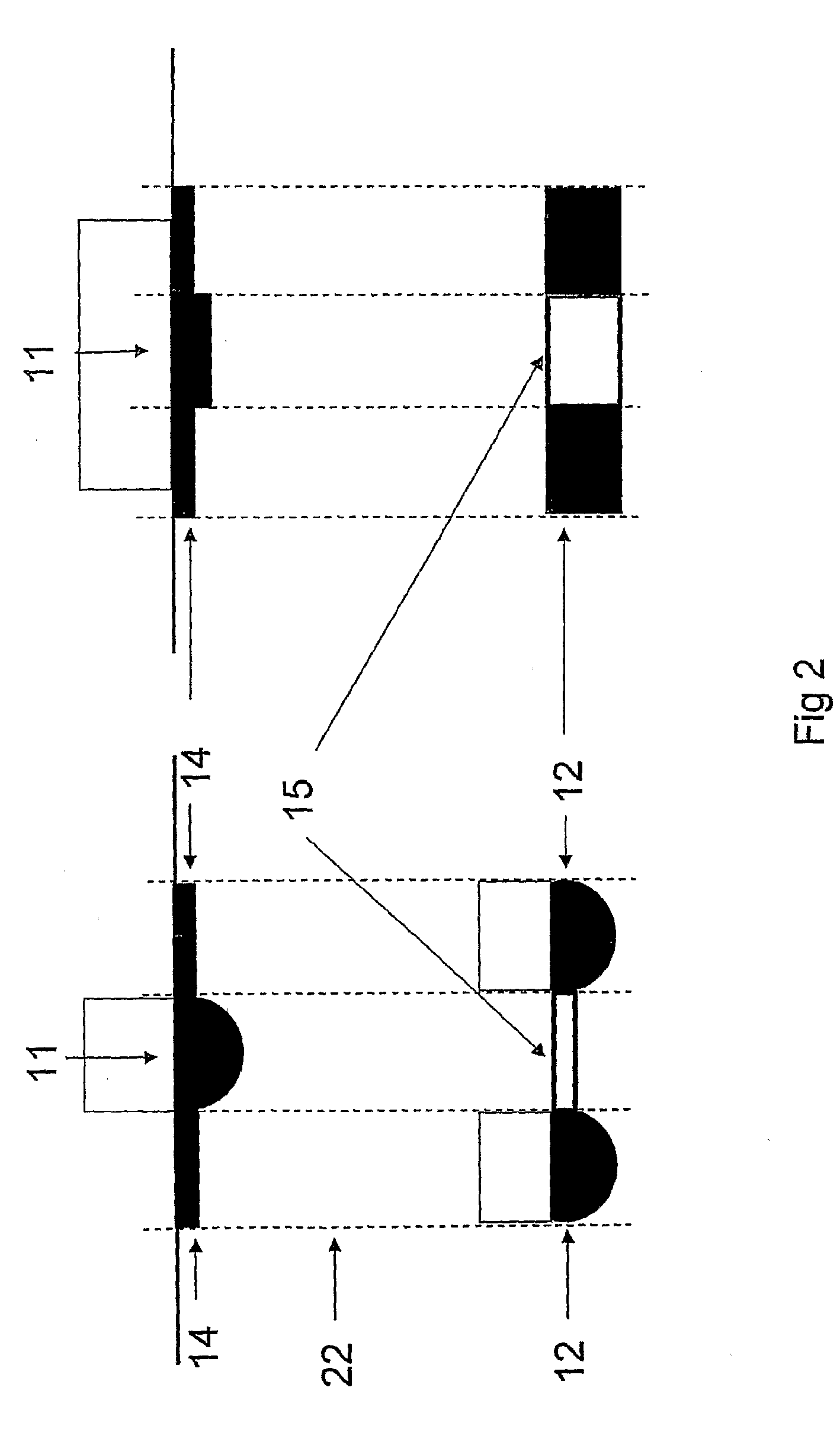
[0032]As shown in FIG. 2 the indicator bars and elongated strips may represent the upper surface of elongated members having either a semi-circular or rectangular cross section, and the warning strips may represent the lower surface of a groov...
second embodiment
[0036]FIG. 7 shows rear cross sectional view of the second embodiment, illustrating that the indicator bars and elongated strips may represent the top surface of elongated bodies having a rectangular cross section, and that the warning strips may represent the bottom surface of a groove or trough. The cross sections shown are only illustrative, and other cross sections are possible.
[0037]FIG. 8 shows the visual image of the different positions of the eyes in relation to the club head of the second embodiment. FIG. 8A shown the image when eyes are perfectly above the club head center plane. FIG B1 shows the image when eyes are slightly misaligned to the inside of the plane revealing the warning strip 32 on the right side. The lower elongated strip 34 is hidden under the upper left indicator bar 33. FIG C1 shows the image when the eyes are to the outside of the vertical plane revealing the warning strip 35 on the left side. The lower elongated strip 34 is hidden under the upper right ...
third embodiment
[0039]FIG. 10 shows the alignment system according to the invention. This “window” solution comprises a warning strip 44 on the lower part of a window member comprising a front frame portion 45, a back frame portion 48, a bottom frame portion 47, a top frame portion 41 defining an indicator bar 42 and a window opening 43. Warning strip 44 is the concave surface of bottom portion 47, and is the same width as indicator bar 42. This embodiment can either be used singly, or two such windows can be arranged on the alignment section of the putter, spaced apart at a distance slightly less than the width of a golf ball.
[0040]FIG. 11 shows that when slightly misaligned to the inside of the center plane FIG B1, then the warning strip 44 immediately appears. When further misaligned as in FIG B2, then more of the warning strip 44 appears. When misaligned to the other side of the vertical plane, then the warning color appears on the same side. Because of the curved surface of warning strip 44, t...
PUM
 Abstract
Description
Claims
Application Information
 - R&D Engineer
- R&D Manager
- IP Professional
- Industry Leading Data Capabilities
- Powerful AI technology
- Patent DNA Extraction
Browse by: Latest US Patents, China's latest patents, Technical Efficacy Thesaurus, Application Domain, Technology Topic, Popular Technical Reports.
© 2024 PatSnap. All rights reserved.Legal|Privacy policy|Modern Slavery Act Transparency Statement|Sitemap|About US| Contact US: help@patsnap.com


