Dynamic Stabilization Device for Spine

a stabilization device and spine technology, applied in the field of spinal implantation, can solve the problems of inability to facilitate inward tension, inability to provide the same degree of flexibility and support for the spine, and the method and system taught in this chapter lacks well defined connection points for the springs

Active Publication Date: 2009-02-19
JMEA CORP
View PDF83 Cites 209 Cited by
  • Summary
  • Abstract
  • Description
  • Claims
  • Application Information

AI Technical Summary

Benefits of technology

[0026]In another aspect, the effective fatigue limit is between 10 percent of the fatigue limit and 75 percent of...

Problems solved by technology

Generally, spiral cut grooves may not provide the same degree of flexibility and support as a spring.
First, the methods and systems taught here lack well defined connection points for the springs, and instead rely on stops or sleeve assisted stops.
Also, in these systems, the springs may not facilitate inwar...

Method used


Image

  • Dynamic Stabilization Device for Spine
  • Dynamic Stabilization Device for Spine
  • Dynamic Stabilization Device for Spine

Examples


Embodiment Construction

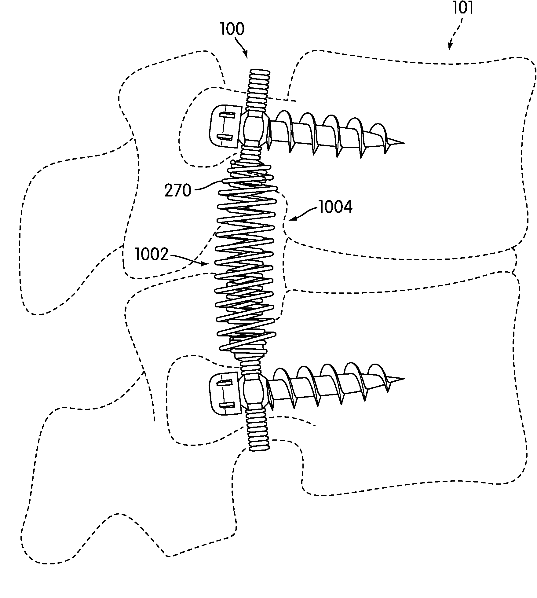
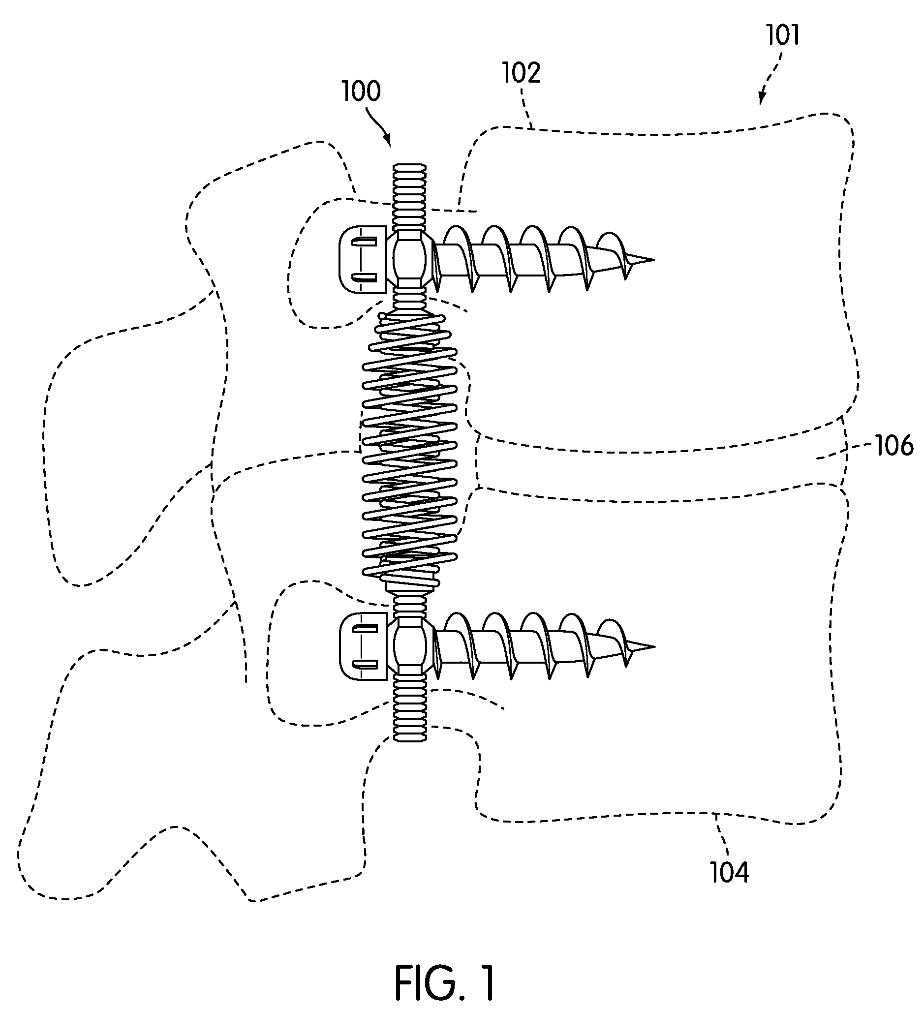
[0078]FIG. 1 is a side view of a preferred embodiment of dynamic stabilization device 100. In this embodiment, dynamic stabilization device 100 is configured to attach to spine 101. Generally, dynamic stabilization device 100 may be applied in surgeries intended to address disc degenerative diseases, spinal stenosis, spondylolisthesis, scoliosis, as well as other spinal problems. Dynamic stabilization device 100 may allow for dynamic support to spine 101 to provide immediate postoperative stability when used in the case of disc replacement or nucleus replacement.

[0079]In this embodiment, dynamic stabilization device 100 is configured to attach to first vertebra 102 and second vertebra 104. First vertebra 102 and second vertebra 104 are further associated with spinal disc 106. Spinal disc 106 is disposed between vertebrae 102 and 104. In some embodiments, spinal disc 106 could be surgically altered, including reduction in size. In other embodiments, spinal disc 106 may be a disc impl...


PUM


Abstract

A dynamic stabilization device is disclosed. The device includes a dual spring member comprising an outer spring and an inner spring that have approximately equal working lengths. The dynamic stabilization device is also configured so that the dual spring member does not undergo stresses greater than an effective fatigue limit that is related to a fatigue limit of the spring.

Description

BACKGROUND OF THE INVENTION[0001]1. Field of the Invention[0002]The present invention relates generally to spinal implantations and in particular to a dynamic stabilization device configured for the spine.[0003]2. Description of Related Art[0004]Methods of spinal stabilization have previously been proposed. Previous methods have incorporated various components configured to provide some type of flexibility. Jahng et al. (U.S. patent number 2005 / 0203513) teaches a spinal stabilization device. The stabilization device includes a longitudinal member having first and second ends as well as a flexible section disposed between the first and second ends. Jahng further teaches a cross sectional profile for the flexible section that is different than the cross sectional profiles of the first and second ends. Jahng teaches a flexible section that includes spiral cut grooves to improve flexibility.[0005]Generally, spiral cut grooves may not provide the same degree of flexibility and support as...

Claims


Application Information

Patent Timeline
IPC IPC(8): A61B17/70A61B17/56A61B17/04A61B17/58
CPCA61B17/7004A61B17/7032A61B17/7028A61B17/7005A61B17/7007A61B17/7008A61B17/7019A61B17/702A61B17/7026A61B17/7029A61B17/7031
Inventor BHATNAGAR, MOHIT K.SACK, JAMES A.YEH, JACK Y.
Owner JMEA CORP
Why Eureka
Try Eureka