Eureka AIR delivers breakthrough ideas for toughest innovation challenges, trusted by R&D personnel around the world.

Externally Baffled Ridge Vent With Fastener

Inactive Publication Date: 2009-02-26
KASEDA MARIO
View PDF11 Cites 13 Cited by
  • Summary
  • Abstract
  • Description
  • Claims
  • Application Information

AI Technical Summary

Benefits of technology

[0008]There is provided a roof ridge vent. The roof ridge vent includes an elongate top wall secured to a pair of opposed outer sidewalls depending generally outwardly and generally downwardly from peripheral longitudinal edges of the top wall, and a pair of opposed end walls depending from opposite ends of the top

Problems solved by technology

Reliably heating and cooling building structures under those roofs can pose a number of challenges.
Current attempts to secure roof ridge vents have been largely unsuccessful.

Method used


Image

  • Externally Baffled Ridge Vent With Fastener
  • Externally Baffled Ridge Vent With Fastener
  • Externally Baffled Ridge Vent With Fastener

Examples


Embodiment Construction

[0010]Preliminarily, it should be noted that certain terms used herein, such as for example above, below, upper, lower, left and right, are used to facilitate the description of the invention. Unless otherwise specified or made apparent by the context of the discussion, such terms and other directional terms should be interpreted with reference to the figure(s) under discussion. Such terms are not intended as a limitation on the position in which the invention or components may be used. Indeed, it is contemplated that the components of the invention may be easily positioned in any desired orientation for use. Likewise, numerical terms such as for example “first”, and “second” are not intended as a limitation or to imply a sequence, unless otherwise specified or made apparent by the context of the discussion. The term “operatively connected” is understood to include a linking together of the portions under consideration and may include a physical engagement and / or a functional or ope...


PUM


Abstract

A roof ridge vent includes a receptacle adapted to receive a fastener and located in the top wall of the roof ridge vent. The fastener is embedded in the top wall and positioned in the receptacle.

Description

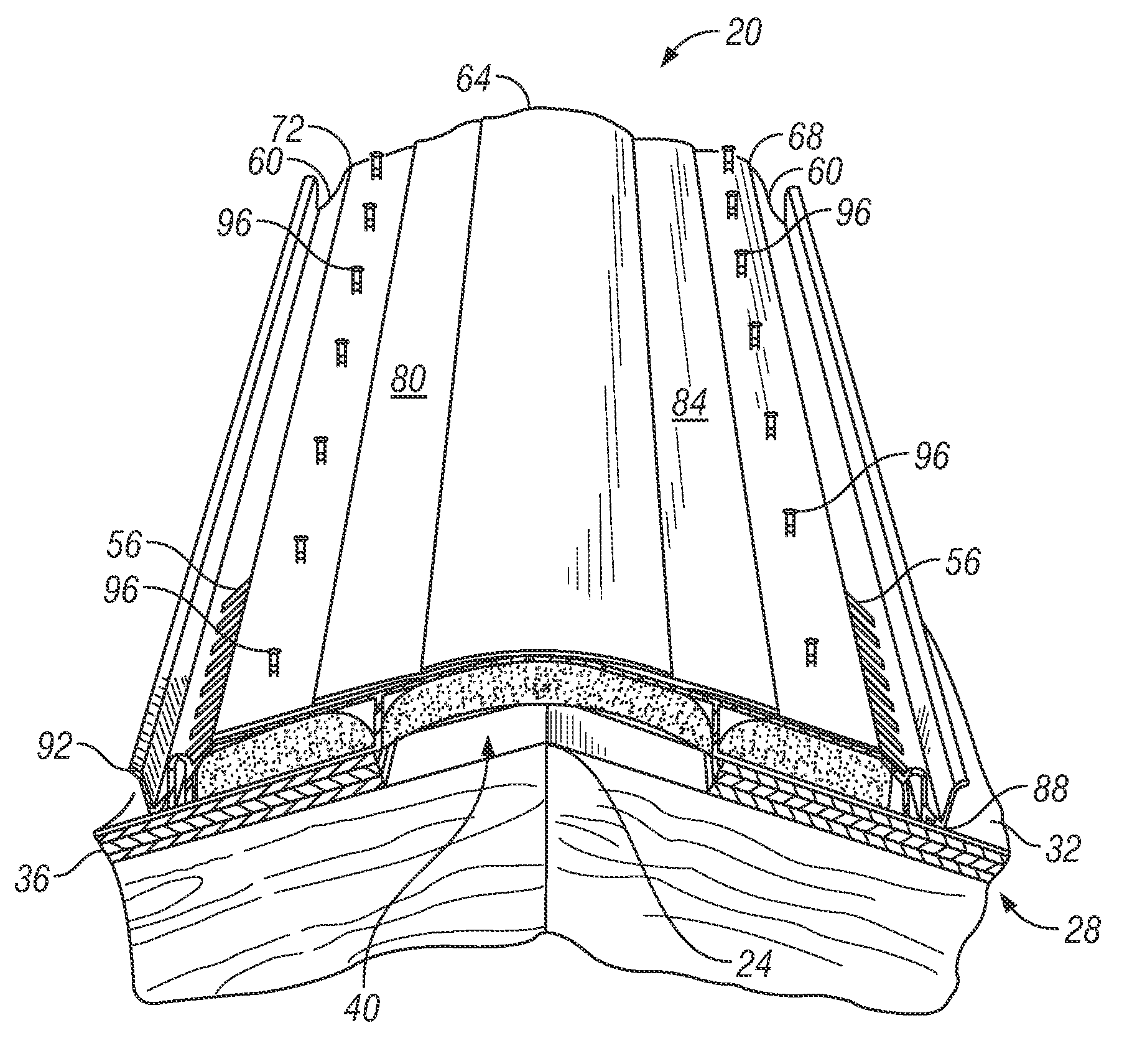
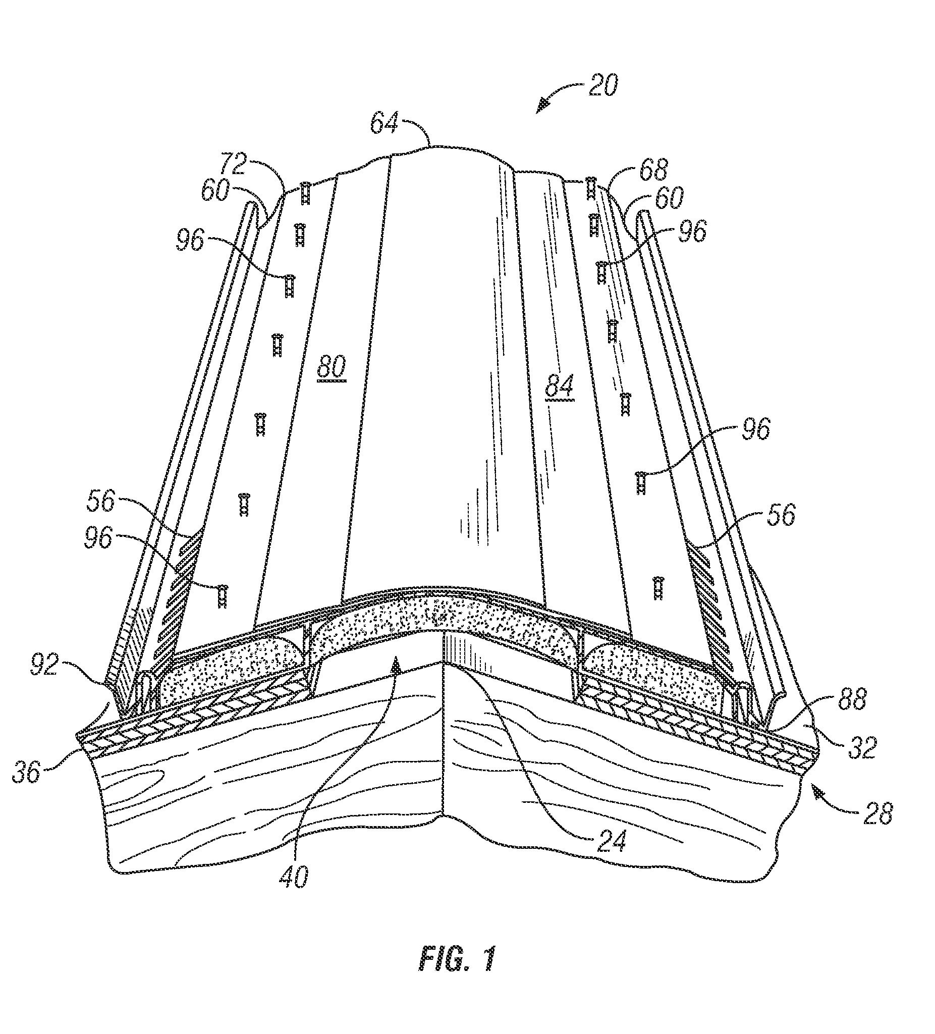
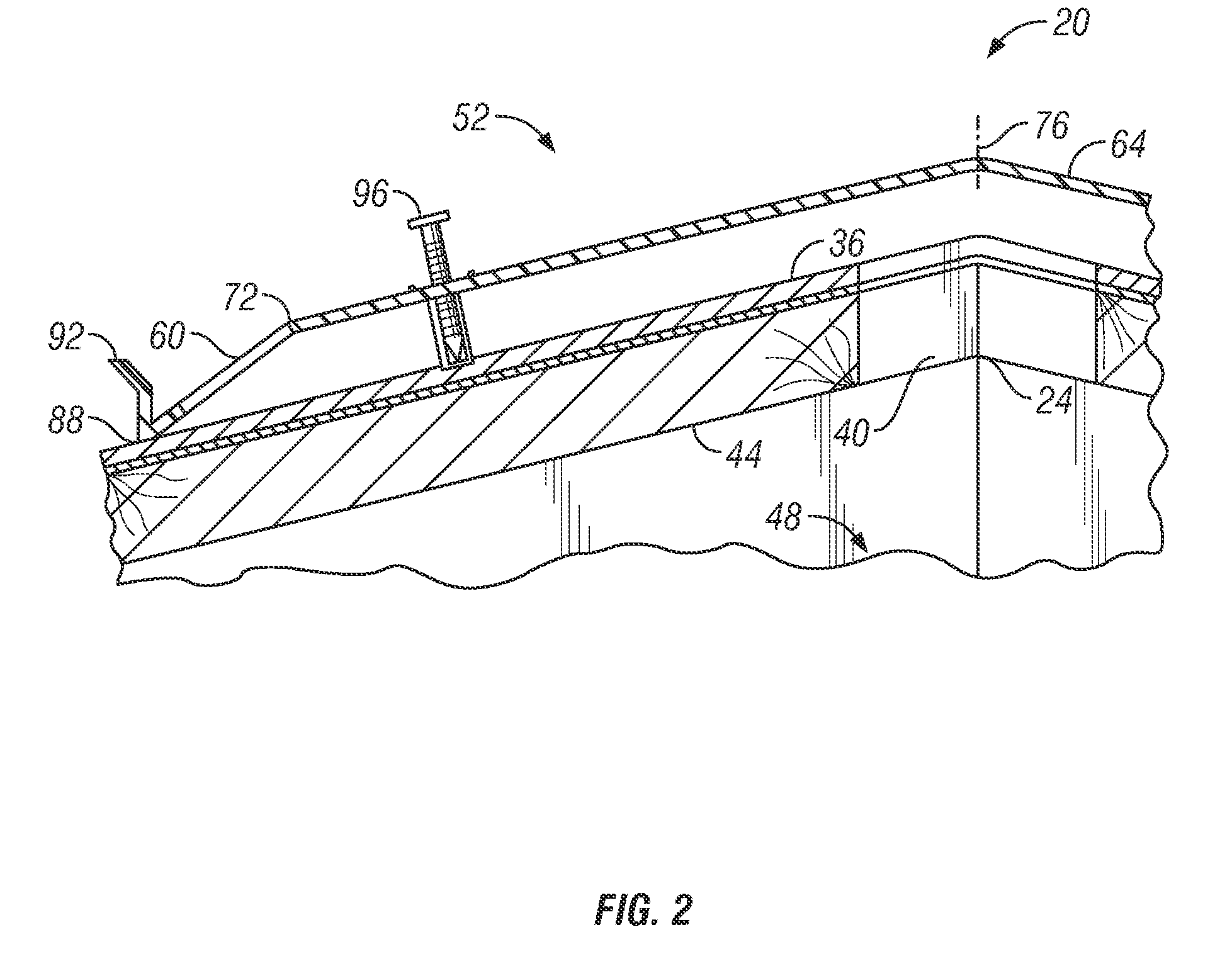
BACKGROUND OF THE INVENTION[0001]A residential and commercial roof generally serves utilitarian functions for building structures. Reliably heating and cooling building structures under those roofs can pose a number of challenges.[0002]Roof ridge vents may be employed to promote air circulation in attics. Current attempts to secure roof ridge vents have been largely unsuccessful. There remains a long-felt need for a suitable means of making and installing roof ridge vents.BRIEF DESCRIPTION OF THE DRAWINGS[0003]FIG. 1 is a perspective view in elevation of a roof ridge having an installed roof ridge vent in accordance with the present invention.[0004]FIG. 2 is a cross-sectional view in elevation of a roof ridge vent according to FIG. 1.[0005]FIG. 3 is a perspective top view of a roof ridge vent according to FIG. 1 with a portion cut out to show detail.[0006]FIG. 4 is a bottom plan view of the roof ridge vent similar to FIG. 1 having four sections.[0007]FIG. 5 is a cross-sectional view...

Claims


Application Information

Patent Timeline
IPC IPC(8): E04D13/17
CPCE04D13/174
Inventor KASEDA, MARIO
Owner KASEDA MARIO
Why Eureka
Eureka Blog
Learn More