Case structure having conductive pattern and method of manufacturing the same

a technology of conductive pattern and case structure, which is applied in the direction of casing/cabinet/drawer details, electrical apparatus casing/cabinet/drawer, coupling device connection, etc., can solve the problems of difficult to reduce the size of the mobile communication terminal, damage to the external antenna,

Inactive Publication Date: 2009-02-26
SAMSUNG ELECTRO MECHANICS CO LTD
View PDF3 Cites 17 Cited by
  • Summary
  • Abstract
  • Description
  • Claims
  • Application Information

AI Technical Summary

Problems solved by technology

Further, when the mobile communication terminal drops, the external antenna may be damaged.
However, a physi

Method used


Image

  • Case structure having conductive pattern and method of manufacturing the same
  • Case structure having conductive pattern and method of manufacturing the same
  • Case structure having conductive pattern and method of manufacturing the same

Examples


Embodiment Construction

[0034]Exemplary embodiments of the present invention will now be described in detail with reference to the accompanying drawings.

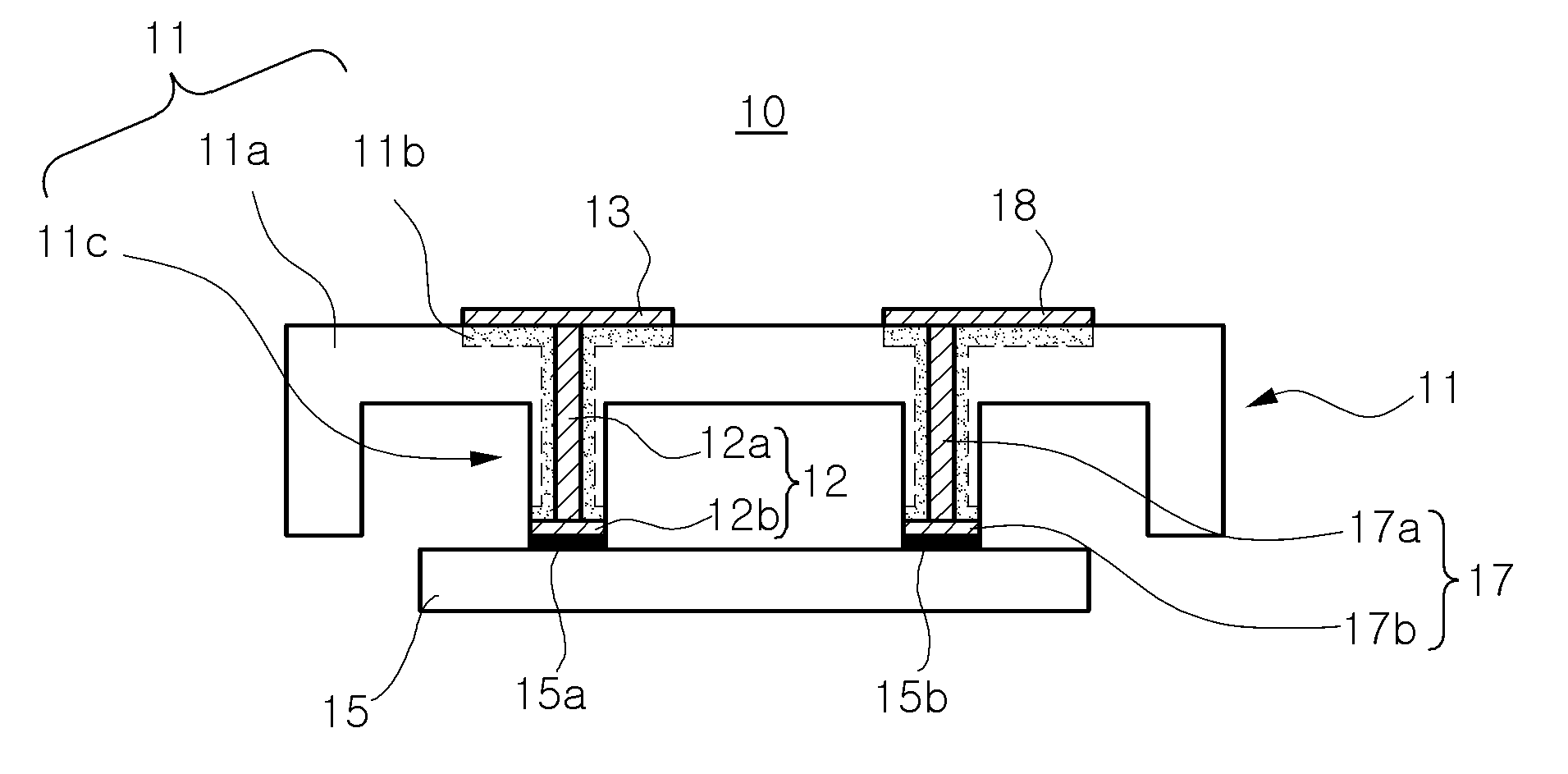
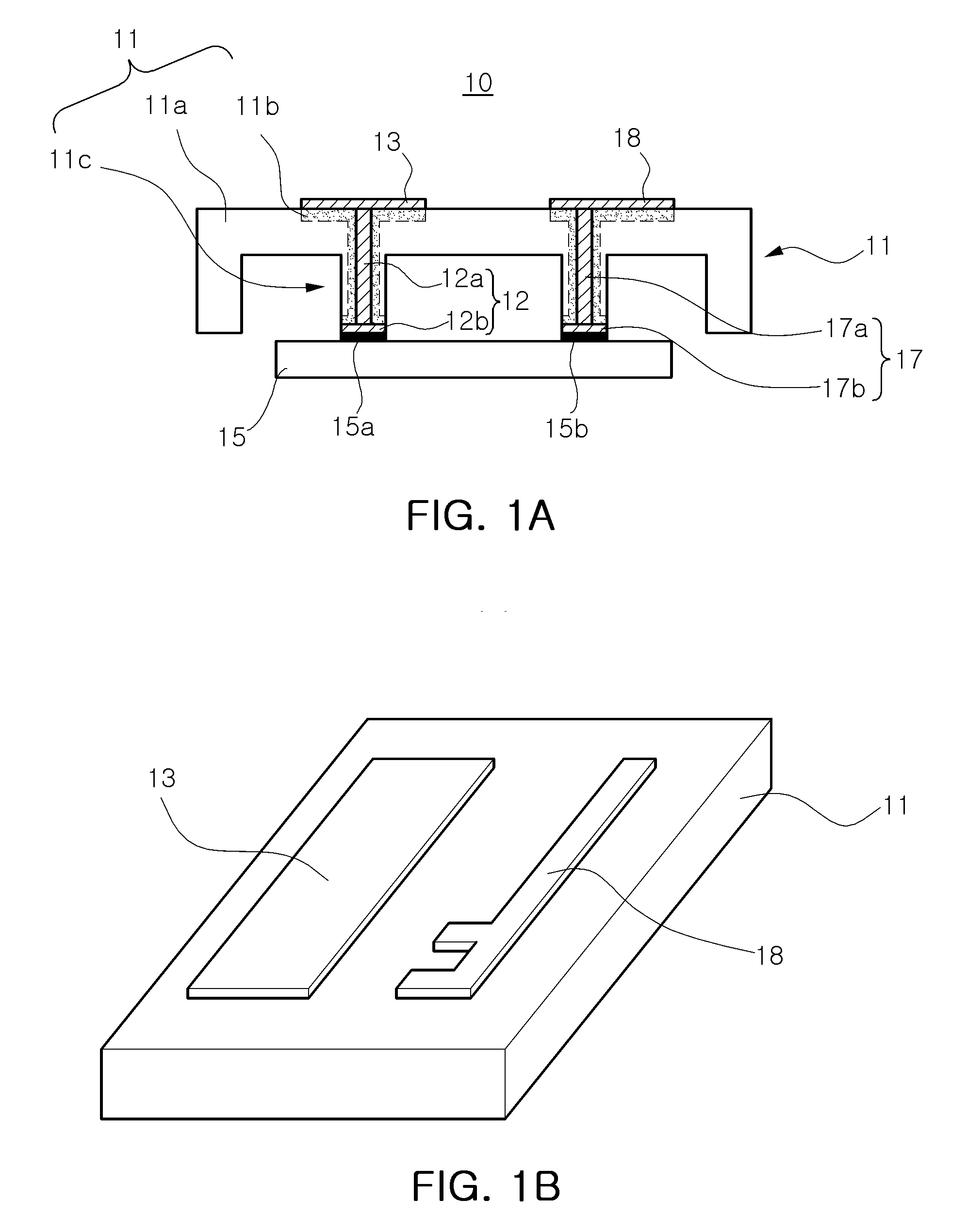
[0035]FIG. 1A is a cross-sectional view illustrating a case structure having a conductive pattern according to an exemplary embodiment of the present invention. FIG. 1B is a perspective view illustrating the case structure having a conductive pattern according to the exemplary embodiment of the present invention.

[0036]Referring to FIGS. 1A and 1B, a case structure according to the embodiment of the invention may include a case 11, conductive vias 12 and 17, and conductive patterns 13 and 18.

[0037]The case 11 may be a case of a mobile communication terminal. In this embodiment, one side of the case of the mobile communication terminal is only shown.

[0038]One or more via holes that pass through the inside and outside of the case 11 may be formed in the case 11. Conductive vias are formed within the via holes to electrically connect the conductive patterns 13...


PUM


Abstract

There is provided a case structure having a conductive pattern and a method of manufacturing the same. A case structure having a conductive pattern according to an aspect of the invention includes a case having at least one via hole formed therein; at least conductive pattern formed on an outer surface of the case; and a conductive via formed within the via hole and electrically connecting the at least one conductive pattern to a board inside the case.

Description

CROSS-REFERENCE TO RELATED APPLICATIONS[0001]This application claims the priority of Korean Patent Application No. 2007-0084429 filed on Aug. 22, 2007, in the Korean Intellectual Property Office, the disclosure of which is incorporated herein by reference.BACKGROUND OF THE INVENTION[0002]1. Field of the Invention[0003]The present invention relates to case structures and a method of manufacturing the same, and more particularly, to a case structure having a conductive pattern formed at a surface thereof that can be electrically connected to a board inside the case, and a method of manufacturing the same.[0004]2. Description of the Related Art[0005]Recently, mobile communication terminals, such as a GPS, a PDA, a cellular phone, and a wireless laptop computer, have put into widespread use. Correspondingly, there is a need for small, lightweight, and thin mobile communication terminals. In order to satisfy the need, efforts have been made to reduce the volume of the mobile communicatio...

Claims


Application Information

Patent Timeline
IPC IPC(8): H01R13/46H01Q1/38B05D5/12
CPCH05K1/0284H05K1/119H05K3/426H05K2201/0999H05K2201/09045H05K2201/09118H05K2201/09481H05K9/0045H05K5/02
Inventor JEON, DAE SEONGBAE, SANG WOOSUNG, JAE SUK
Owner SAMSUNG ELECTRO MECHANICS CO LTD
Why Eureka
Try Eureka