Shelter System

a technology of a shelter and a sleeve, which is applied in the direction of tents/canopies, building types, constructions, etc., can solve the problem of inability to withstand unexpected loads

Inactive Publication Date: 2009-03-05
STANLEY DAVID J +1
View PDF8 Cites 23 Cited by
  • Summary
  • Abstract
  • Description
  • Claims
  • Application Information

AI Technical Summary

Problems solved by technology

In spite of the apparent ease and simplicity of erecting structures such as those illustrated in the foregoing notations of exemplary prior art, the biggest difficulty with the prior art concepts is their inability to withstand unexpected loads such as those imposed by high wind conditions.

Method used


Image

  • Shelter System
  • Shelter System
  • Shelter System

Examples


Embodiment Construction

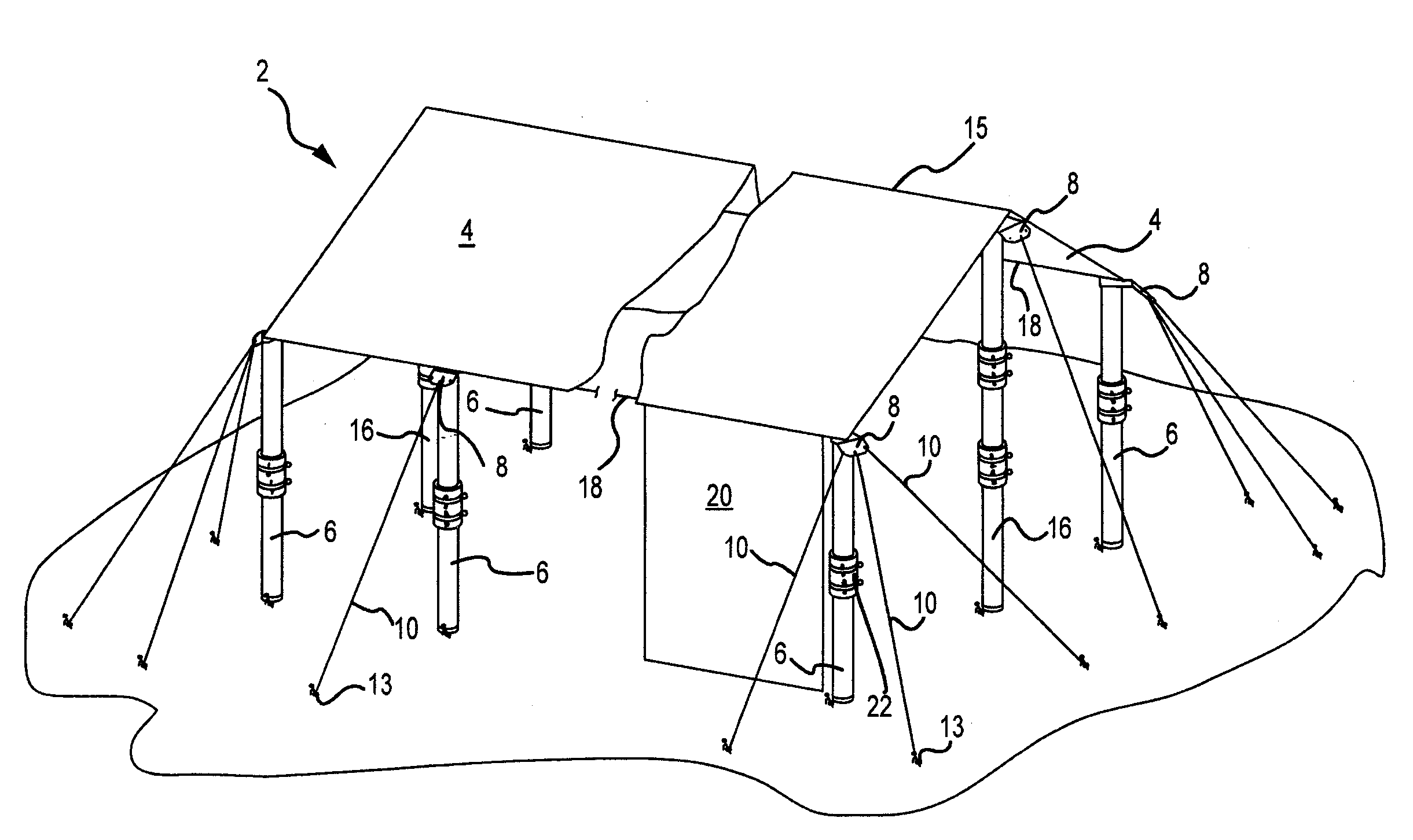
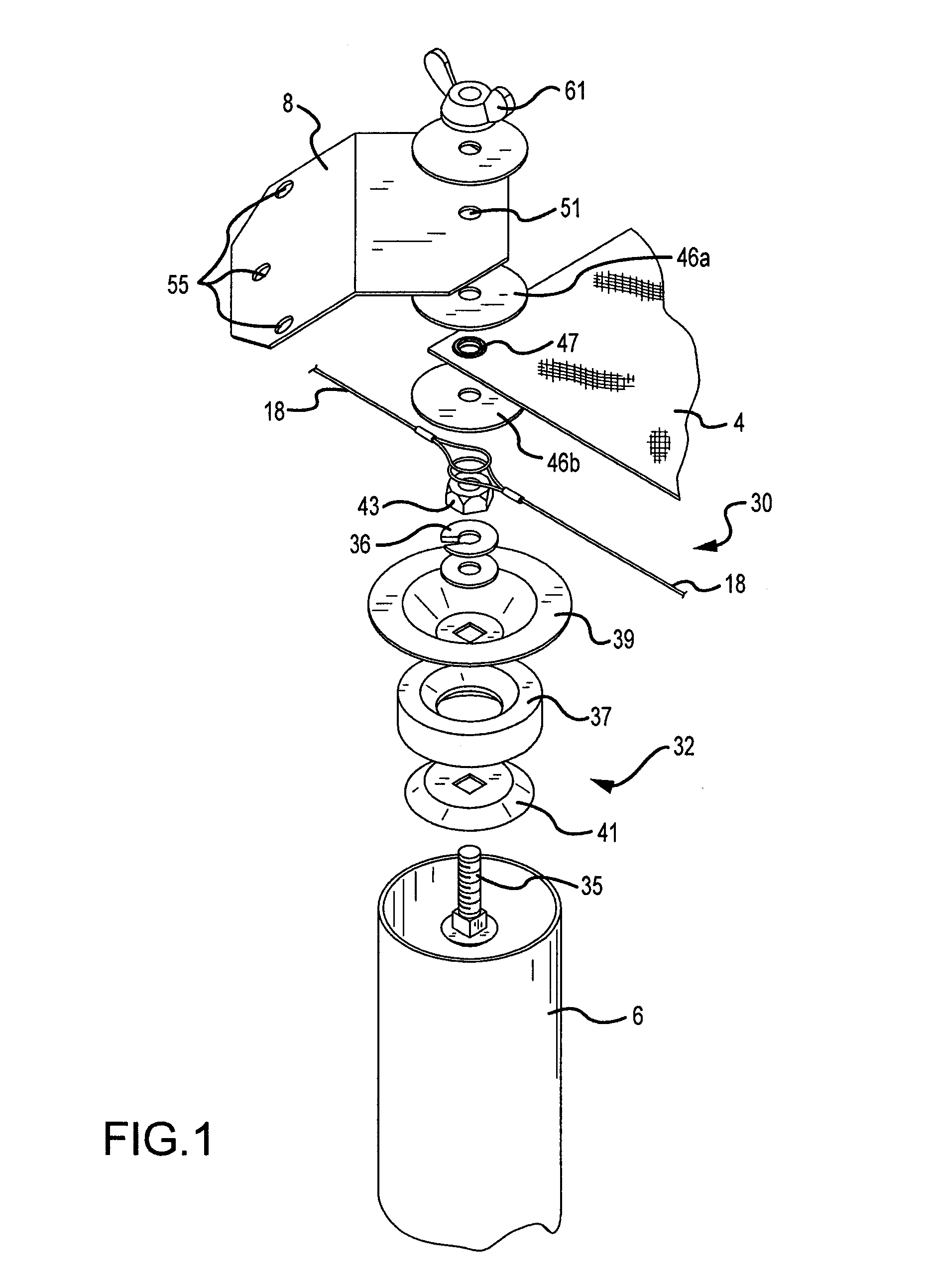
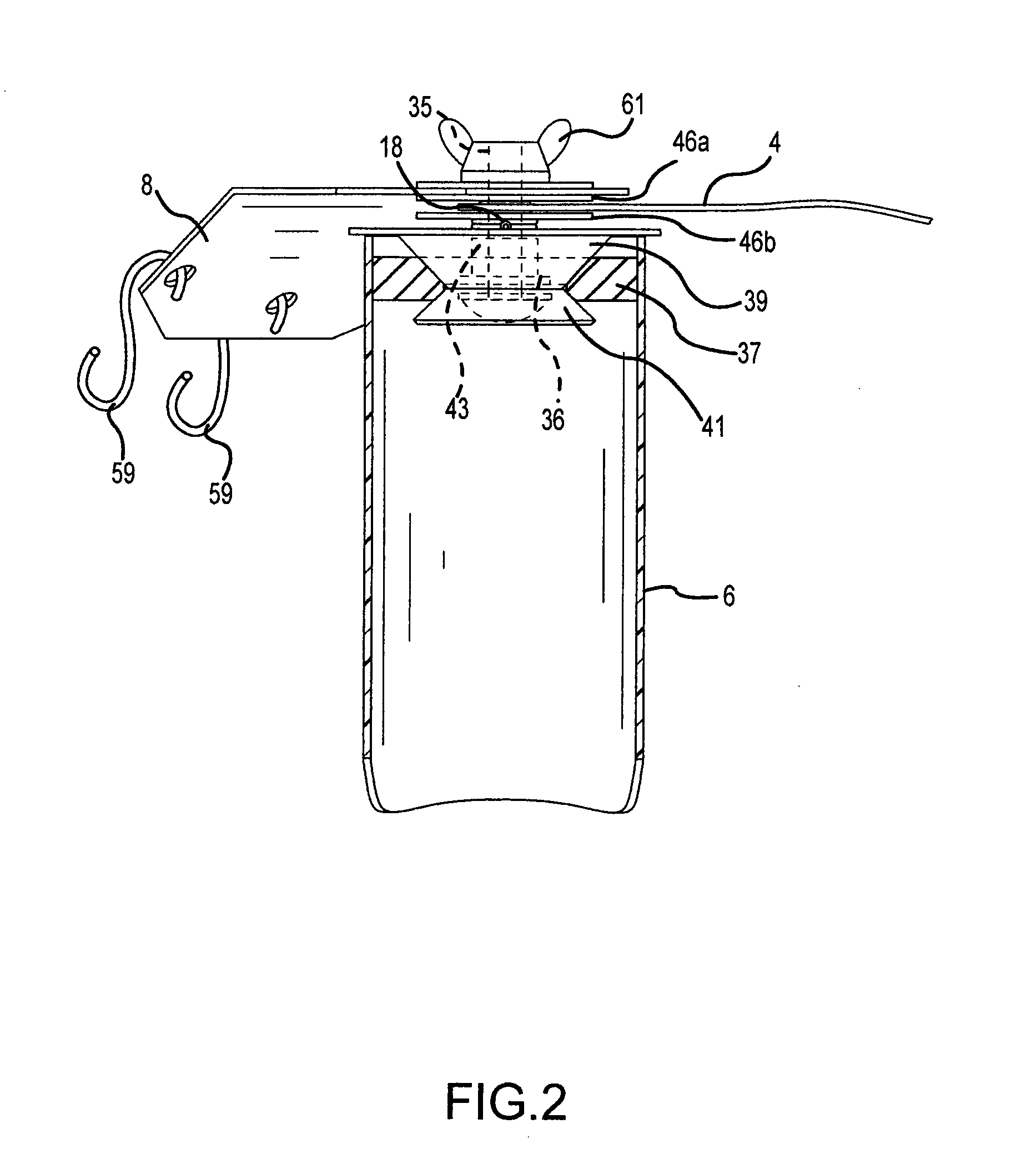
[0012]An exemplary shelter system 2 of the present invention is shown in FIG. 4, to which reference is now made. A fabric, plastic or composite canopy 4 is supported by a plurality of spaced apart tubular perimeter support poles 6. The support poles are preferably made of ABS plastic pipe, or a similar product. Each of the perimeter poles contains a plate bracket 8 secured by a connector assembly to the pole's upper end. The bracket 8 is intended to be the anchor point for one or more ground lines 10. Preferably, the ground lines are fabric straps; however rope, cables and the like may be used. The lower ends of the ground lines are secured into the underlying ground with conventional stakes 13. The center of the canopy is preferably elevated over the height of the perimeter to form a ridge 15 through the use of extended length ridge line supporting poles 16. A horizontally disposed cable 18 may be strung taught between the connector assemblies of adjacent perimeter supporting poles...


PUM


Abstract

A shelter system comprising a flexible canopy supported by a plurality of cylindrical tubular poles where the poles comprise a novel assembly for attaching the canopy, ground straps and auxiliary cables to the top of the poles, including an expansion plug disposed in the top end of each tubular pole for anchoring a shaft disposed coaxially with the longitudinal axis of the tube which shaft carries at least one bracket plate and a portion of the canopy.

Description

FIELD OF THE INVENTION[0001]The present invention relates generally to a system of components that cooperate to form a temporary shelter of the type having perimetrical supporting poles and a fabric canopy structure for a top.BACKGROUND OF THE INVENTION[0002]The prior art is abundantly provided with apparatus and methods for constructing temporary shelters such as fully enclosed tents and canopy covers, with or without side panels. The detailed construction of the supporting poles, or legs, of the structure is frequently material to the novelty of the structure. Exemplary of such apparatus is the portable umbrella shelter shown in U.S. Pat. No. 5,287,872 where the central supporting pole functions in a number of different capacities. U.S. Pat. No. 4,941,500 discloses a knockdown canopy shelter in which the extensible support poles are extended to form support for the canopy structure. U.S. Pat. No. 4,690,161 illustrates a canopy supported by a central pole and a number of peripheral...

Claims


Application Information

Patent Timeline
Patent Type & Authority Applications(United States)
IPC IPC(8): E04H15/34E04H15/32E04H15/54
CPCE04H15/64E04H15/60
Inventor STANLEY, DAVID J.FORMAN, JEROME I.
Owner STANLEY DAVID J
Why Eureka
Try Eureka