Suture passer

a technology of suture and loop, which is applied in the field of looped suture passer, can solve the problems of difficult suture passing, affecting the maneuverability of the device, and difficult suture passing through the vaginal wall,

Active Publication Date: 2009-03-12
BOSTON SCI SCIMED INC
View PDF49 Cites 32 Cited by
  • Summary
  • Abstract
  • Description
  • Claims
  • Application Information

AI Technical Summary

Problems solved by technology

Passing sutures through the vaginal wall, however, is difficult as there is limited space to work in.
Because passing a suture is often difficult due to the limited space available to work in, devices and techniques have been developed to assist a person, such as a surgeon, in manipulating sutures.
In some case, the plunger-type devices also have obtrusive handles, which can impair maneuverability of the device when working in confined spaces.
As such, the confined surgical work space can become cluttered with devices and thus impair maneuverability of individual devices.

Method used


Image

  • Suture passer
  • Suture passer
  • Suture passer

Examples


Embodiment Construction

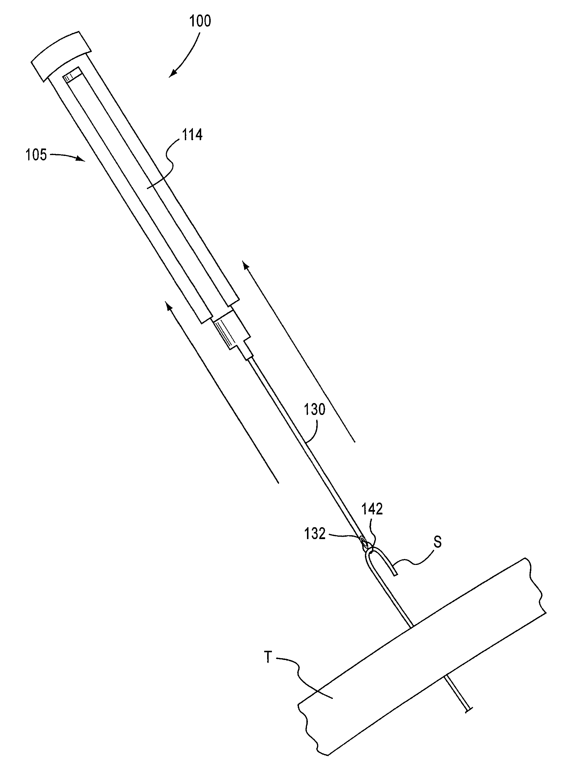
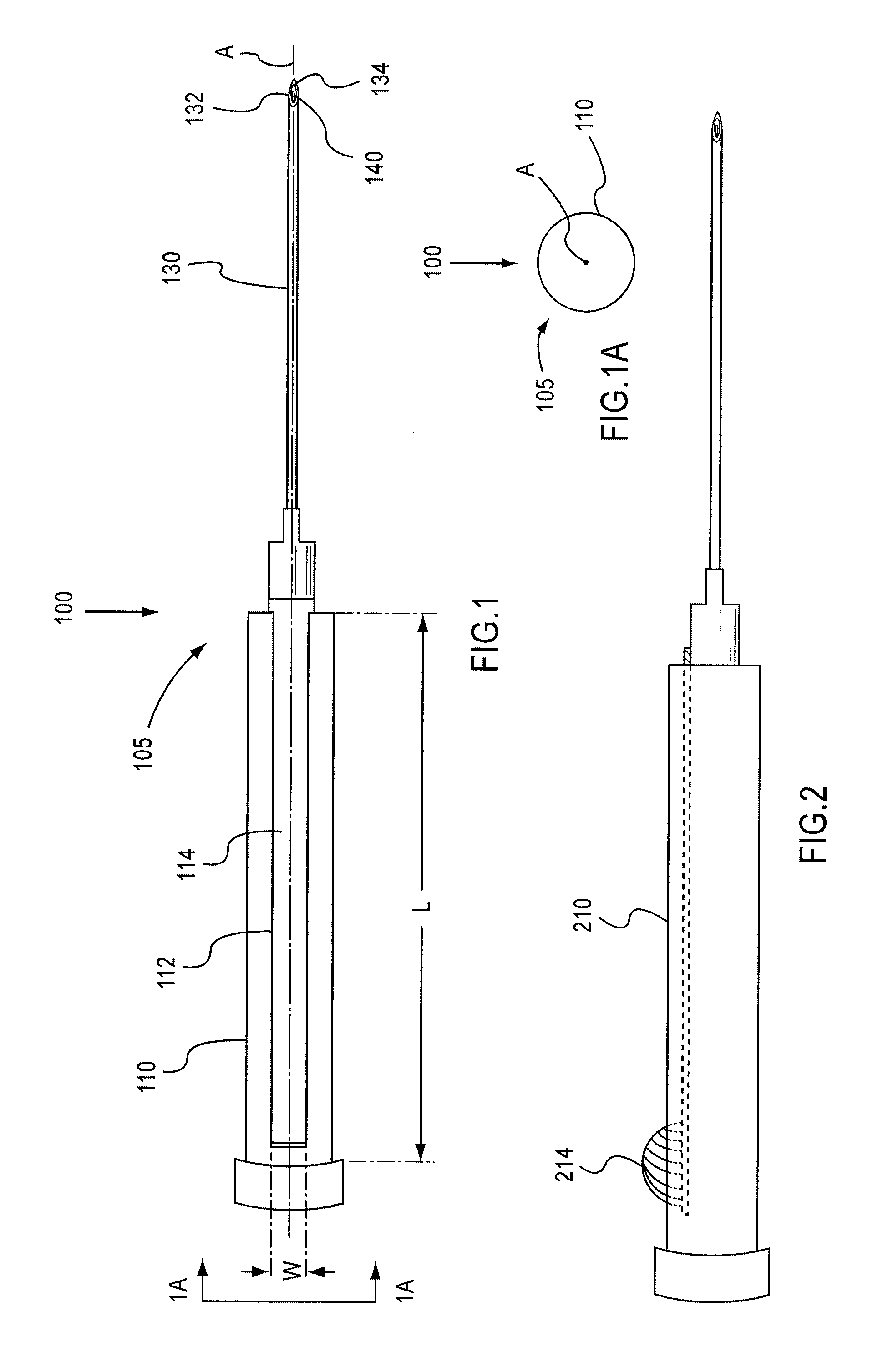
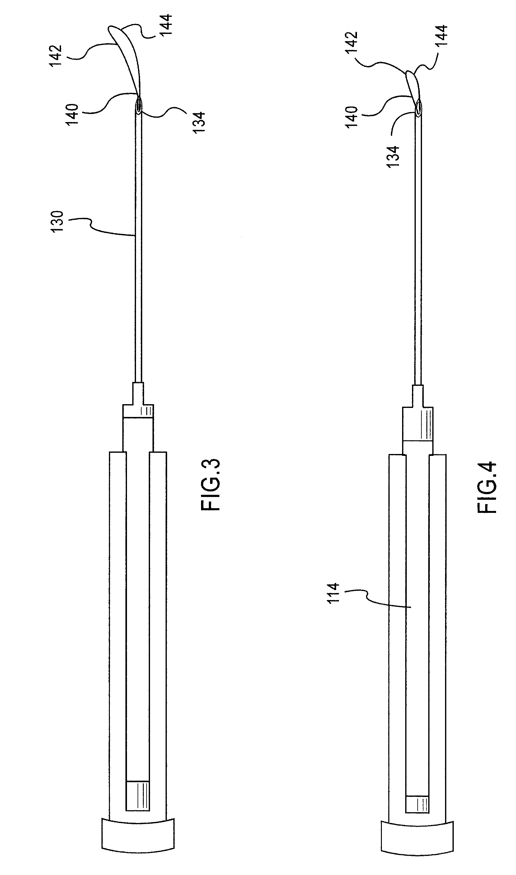
[0019]As illustrated in FIG. 1, an apparatus 100 according to an embodiment of the invention includes an elongate member 105, an actuator 114, and a thread member 140. The elongate member 105 has a handle portion 110 and a shaft portion 130. The elongate member 105 extends along and defines a central axis A. The shaft portion 130 defines a lumen 132 along central axis A and has a distal opening 134. A portion of a thread member 140 is disposed within the lumen 132 of the shaft portion 130. As illustrated in FIGS. 1 and 1A, the apparatus 100 is compactly configured. Specifically, the elongate member 105 is substantially cylindrical and has no large protrusions perpendicular to axis A when the apparatus 100 is viewed from an end view.

[0020]The handle portion 110 of the elongate member 105 defines a slot 112. As illustrated in FIG. 1, the slot 112 can be an elongate slot having a length L that is greater than the width W of the slot. The elongate slot 112 extends parallel to the centra...


PUM


Abstract

An apparatus includes an elongate member, an actuator, and a thread member. A portion of the elongate member defines a central axis. The elongate member defines a slot which extends along an axis parallel to the central axis. The actuator is coupled to the elongate member and is accessible through the slot. The actuator is moveable from a first position to a second position different than the first position. The thread member is coupled to the actuator and has a receiving portion. The thread member is moveable from a first position to a second position different than the first position when the actuator is moved from its first position to its second position. A portion of the thread member is disposed within a lumen defined by the elongate member when the thread member is in its first position. At least a portion of the thread member extends from a distal opening defined by the elongate member when the thread member is in its second position.

Description

CROSS-REFERENCE TO RELATED APPLICATIONS[0001]This application claims priority to U.S. Provisional Application Ser. No. 60 / 970,620, entitled “Suture Passer,” filed Sep. 7, 2007, which is incorporated herein by reference in its entirety.BACKGROUND[0002]The invention relates to passing a suture or other thread-like object within a body, and more particularly to a looped suture passer to assist in passing at least a portion of a suture or other thread-like object through bodily tissue.[0003]In various corrective surgeries or implant procedures, bodily tissue must be returned to a certain anatomical position or placed in an improved position. For example, when uterine prolapse occurs, weakened ligaments cause the uterus to descend into the vaginal cavity. One way to correct uterine prolapse requires that the vaginal apex be approximated to the sacrospinous ligament. The uterus is suspended by sutures that are passed through the vaginal wall. Passing sutures through the vaginal wall, howe...

Claims


Application Information

Patent Timeline
Patent Type & Authority Applications(United States)
IPC IPC(8): A61B17/06
CPCA61B17/0485A61B2017/00805A61B2017/4216A61B2017/2212A61B2017/06052
Inventor CHU, MICHAEL S. H.
Owner BOSTON SCI SCIMED INC
Why Eureka
Try Eureka