Damping element for a fuel injection valve

Inactive Publication Date: 2009-03-19
ROBERT BOSCH GMBH
View PDF17 Cites 29 Cited by
  • Summary
  • Abstract
  • Description
  • Claims
  • Application Information

AI Technical Summary

Problems solved by technology

It is disadvantageous that the damping element requires a great deal of axial installat

Method used


Image

  • Damping element for a fuel injection valve
  • Damping element for a fuel injection valve
  • Damping element for a fuel injection valve

Examples


Embodiment Construction

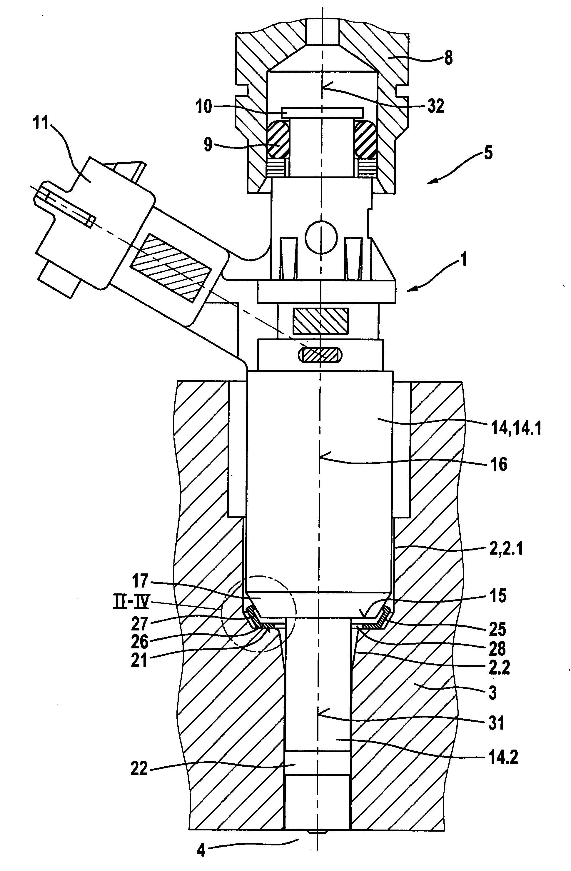
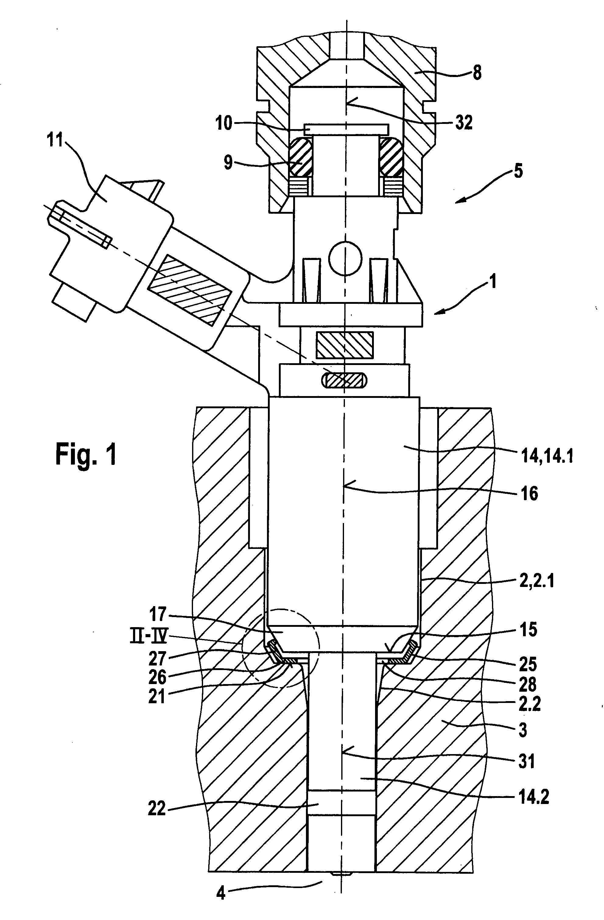
[0018]FIG. 1 is a simplified depiction of a fuel injection valve in a receiving bore of a cylinder head, having a damping element according to the present invention between the fuel injection valve and the cylinder head.

[0019]A fuel injection valve 1 is disposed in a receiving conduit 2 of a cylinder head 3 of an internal combustion engine. Fuel injection valve 1 serves to inject fuel into a combustion chamber 4 of the internal combustion engine and is used, for example, in so-called direct injection. Fuel injection valve 1 has at its inflow end 5, for example, a plug connection to a fuel distribution line 8 that is sealed, for example, by way of a seal 9 between fuel distribution line 8 and an inflow fitting 10 of fuel injection valve 1. Fuel injection valve 1 also has an electrical connector 11 for electrical contacting of an actuator (not depicted) of fuel injection valve 1, for example an electromagnetic or a piezoelectric or magnetostrictive actuator, for actuation of fuel inje...


PUM


Abstract

Known damping elements (25) for a fuel injection valve (1) insertable into a receiving conduit (2) of a cylinder head (3) of an internal combustion engine are disposed between a valve housing (14) of the fuel injection valve (1) and a wall of the receiving conduit (2) of the cylinder head (3). These damping elements (25), inter alia, decrease acoustic transfer from the fuel injection valve to the cylinder head (3). It is disadvantageous that the damping elements known hitherto require a great deal of axial installation space with respect to a valve axis and have comparatively high manufacturing costs. With the damping element (25) according to the present invention, the installation space required is reduced. Provision is made, according to the present invention, for the damping element (25) to be in plate-shaped fashion.

Description

BACKGROUND INFORMATION[0001]The invention is based on a damping element for a fuel injection valve according to the species defined in the main claim.[0002]A damping element for a fuel injection valve insertable into a receiving conduit of a cylinder head of an internal combustion engine, which element is disposed between a valve housing of the fuel injection valve and a wall of the receiving conduit of the cylinder head, is already known from DE 100 38 763. The damping element is made up of two rigid rings between which an elastic intermediate ring is disposed. The damping element, inter alia, decreases acoustic transfer from the fuel injection valve to the cylinder head. It is disadvantageous that the damping element requires a great deal of axial installation space with respect to a valve axis, and has comparatively high manufacturing costs.ADVANTAGES OF THE INVENTION[0003]The damping element according to the present invention having the characterizing features of the main claim ...

Claims


Application Information

Patent Timeline
IPC IPC(8): F02M61/14
CPCF02M61/14F02M2200/30F02M2200/09
Inventor MUELLER, MARTINHUEBEL, MICHAEL
Owner ROBERT BOSCH GMBH
Why Eureka
Try Eureka