Powered insulated staple gun

a staple gun and insulation technology, applied in the field of staple guns, can solve the problems of fatigued operators, time-consuming process, and prolonged use of this device can be fatiguing to operators,

Inactive Publication Date: 2009-03-19
ACTUANT CORP
View PDF9 Cites 7 Cited by
  • Summary
  • Abstract
  • Description
  • Claims
  • Application Information

AI Technical Summary

Problems solved by technology

However, this process is time consuming and can easily fatigue an operator that repeatedly performs the task.
Although manually driven staple guns save time when installing a significant number of staples, prolonged use of this device can be fatiguing to the operator because each staple firing cycle requires the operator to squeeze the handle to compress the spring.

Method used


Image

  • Powered insulated staple gun
  • Powered insulated staple gun
  • Powered insulated staple gun

Examples


Embodiment Construction

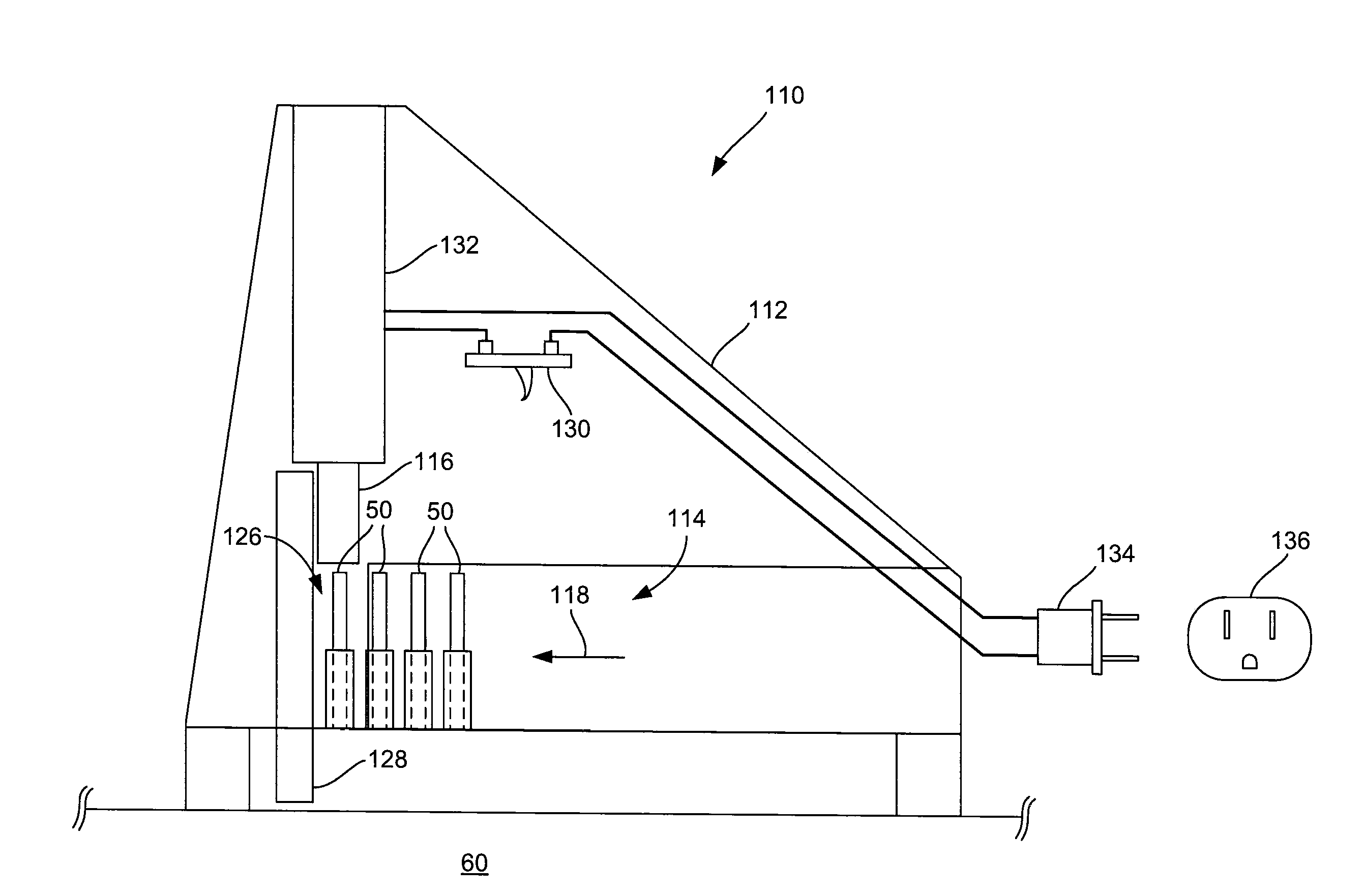
[0024]The present invention generally provides a powered fastening device, such as the powered insulated staple gun 110 shown in FIGS. 4-8, for installing insulated fasteners into a position to hold a cable 70 against a substrate 60. The powered insulated staple gun 110 includes a housing 112 with a fastener recess 114 that accommodates a plurality of insulated staples 50. The insulated staples 50 are biased towards an ejection member 116 due to a biasing force 118 that may be provided, for example, by a compressed spring. During operation, the powered insulated staple gun 110 is positioned adjacent the substrate 60 and the operator preferably applies sufficient force so that the staples 50 penetrate the substrate 60 rather than push off the substrate 60 when they are driven toward it. The operator also actuates a manual actuator, such as a trigger switch 130, to install a staple 50 into the substrate 60. Specifically, actuating the trigger switch 130 creates an operative connection...


PUM


Abstract

A device for applying insulated fasteners to a substrate is disclosed. The device comprises a housing that includes a fastener recess and an ejection recess, and the fastener recess is configured to accommodate insulated fasteners. The device further comprises a powered actuator that includes an ejection member that moves over a range of positions. The ejection member permits one of the insulated fasteners to enter the ejection recess in a retracted position, and the ejection member forces the one of the insulated fasteners to leave the ejection recess in an extended position. A power connector operatively connects the powered actuator to a power source to provide power to move the ejection member. A manual actuator is operatively disposed between the power source and the powered actuator to selectively provide power from the power source to the powered actuator.

Description

CROSS-REFERENCE TO RELATED APPLICATION[0001]This application claims the benefit of U.S. Provisional Patent Application No. 60 / 993,803 filed Sep. 14, 2007, the disclosure of which is hereby incorporated by reference.STATEMENT CONCERNING FEDERALLY SPONSORED RESEARCH OR DEVELOPMENT[0002]Not applicable.FIELD OF THE INVENTION[0003]This invention relates to staple guns and specifically staple guns that apply insulated staples.BACKGROUND OF THE INVENTION[0004]Insulated staples are commonly used to secure cables or wires to a substrate. An insulated staple typically includes two nails and a plastic bridge, or as shown in FIGS. 1b and 3b, is provided as an insulated staple 50 including a metal staple portion 52 with staple legs 54 that extend through a U-shaped plastic bridge 56 to fasten the bridge 56 to a substrate 60. As shown in FIG. 3b, the bridge 56 straddles a cable 70 to reduce the possibility of the metal staple portion 52 contacting or pinching the cable 70.[0005]Insulated fastener...

Claims


Application Information

Patent Timeline
Patent Type & Authority Applications(United States)
IPC IPC(8): B25C5/00B25C5/10
CPCB25C5/15B25C5/0228
Inventor RADLE, PATRICK J.BRAGANZA, AUSTIN R.
Owner ACTUANT CORP
Why Eureka
Try Eureka