Vacuum cleaner having suction path switching unit

Inactive Publication Date: 2009-04-09
SAMSUNG ELECTRONICS CO LTD
View PDF7 Cites 9 Cited by
  • Summary
  • Abstract
  • Description
  • Claims
  • Application Information

AI Technical Summary

Benefits of technology

[0013]The present disclosure provides a vacuum cleaner that switches between suction paths by displacement of at least porti

Problems solved by technology

Also, the present disclosure is not required to overcome the disadvantages described above, and an

Method used


Image

  • Vacuum cleaner having suction path switching unit
  • Vacuum cleaner having suction path switching unit
  • Vacuum cleaner having suction path switching unit

Examples


Embodiment Construction

[0035]Hereinafter, a vacuum cleaner employing a suction path switching unit according to exemplary embodiments of the present disclosure will now be described in detail with reference to the accompanying drawings.

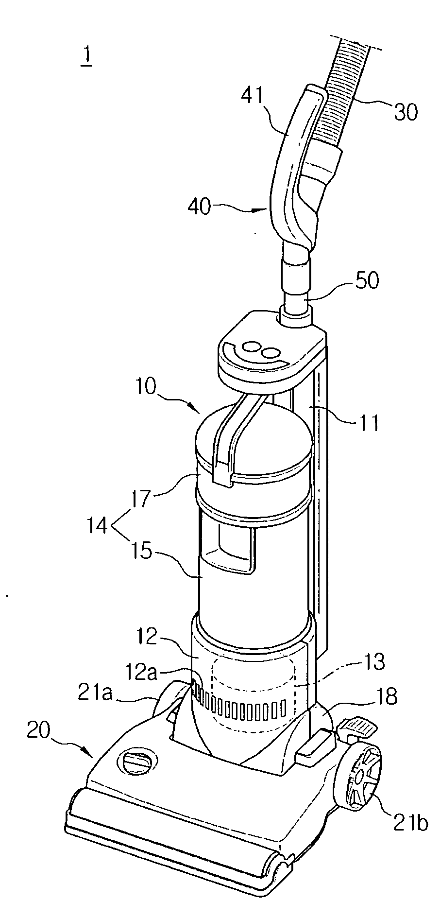
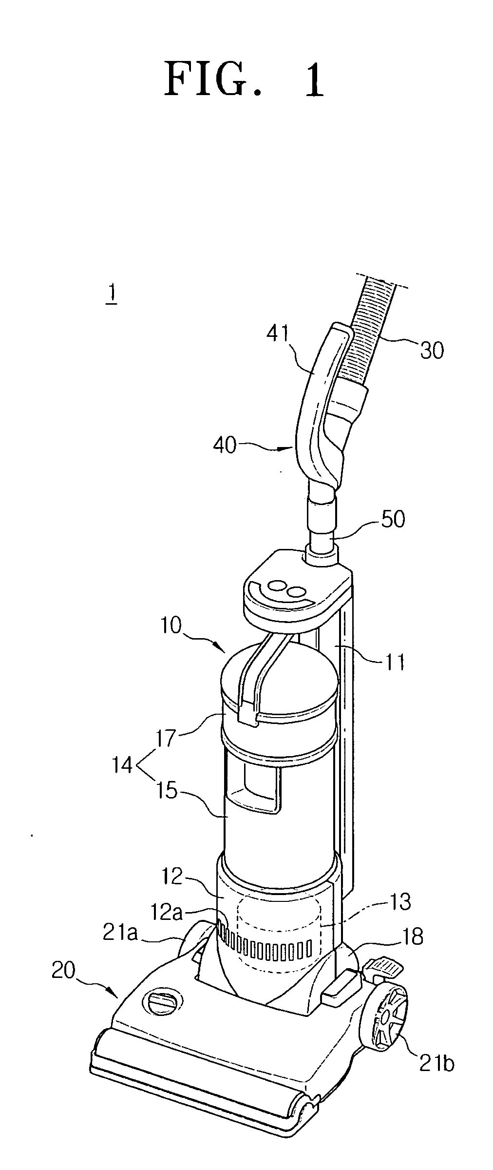
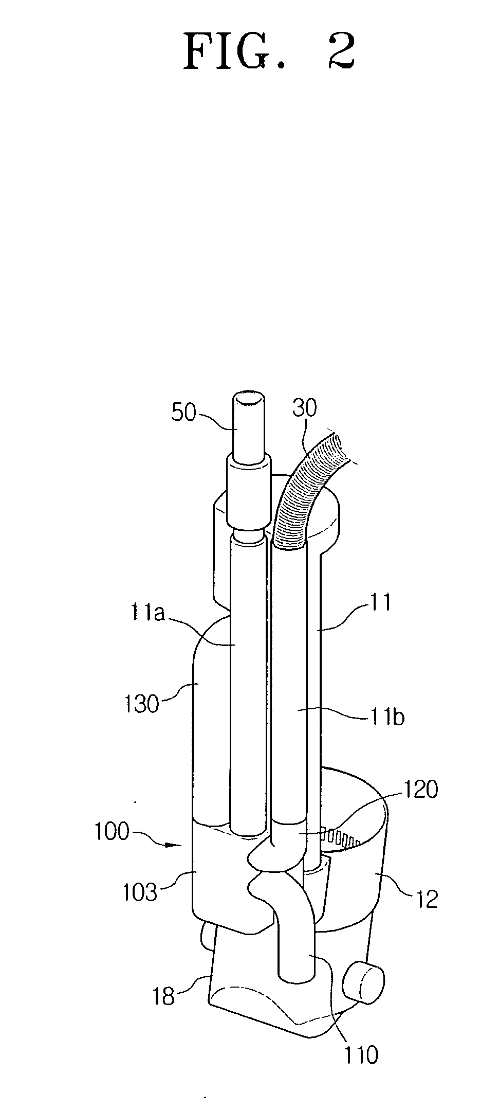
[0036]FIG. 1 shows a vacuum cleaner 1 according to a first exemplary embodiment of the present disclosure. Referring to FIGS. 1 and 2, the vacuum cleaner 1 according to the first exemplary embodiment of the present disclosure. Vacuum cleaner 1 is configured for use in both an upright form and a canister form, includes a main body 10, a suction inlet body 20, an extension pipe assembly 40, and a suction path switching unit 100.

[0037]The main body 10 includes a body frame 11, a suction motor 13, and a dust collecting unit 14. The suction inlet body 20 is hingedly connected to a hinge member 18 on a lower side of the body frame 11, and the suction motor 13 is mounted in a motor casing 12. The dust collecting unit 14, which includes a dust receptacle 15 and a dust separator 17,...


PUM


Abstract

A vacuum cleaner having a suction path switching unit is provided that includes a cleaner body having a body frame; a suction inlet body hinged to the body frame; an extension pipe assembly having a hose and an extension pipe connected in fluid communication with the hose; and a suction path switching unit disposed on the body frame. The suction path switching unit has a switching duct, at least a portion of which is elastically arranged on a suction path to be displaceable on the suction path. As the extension pipe is fixed on or separated from the body frame, the switching duct is selectively displaced to a first position of opening a first suction path flowing from the suction inlet body to the dust collecting unit or a second position of opening a second suction path flowing from the extension pipe to the dust collecting unit.

Description

CROSS-REFERENCE TO RELATED APPLICATIONS[0001]This application is a continuation-in-part of application Ser. No. 12 / 074,824, filed Mar. 6, 2008, in the United States Patent and Trademark Office, which has claimed the benefit under 35 U.S.C. §119(a) from Korean Patent Application No. 10-2007-0101074, filed on Oct. 8, 2007, in the Korean Intellectual Property Office; and claims the benefit under 35 U.S.C. §119(a) from Korean Patent Application No. 10-2008-25616, filed on Mar. 19, 2008, in the Korean Intellectual Property Office, the disclosures of each of which are incorporated herein by reference in their entirety.BACKGROUND OF THE INVENTION[0002]1. Field of the Invention[0003]The present disclosure relates to a vacuum cleaner, and more particularly, to a vacuum cleaner that is capable of selecting a suction path from a suction inlet body or from an extension pipe connected to a cleaner body to draw in dust from a surface to be cleaned using a suction force generated by operation of a...

Claims


Application Information

Patent Timeline
IPC IPC(8): A47L5/00
CPCA47L5/32
Inventor KIM, SEE-HYUNPARK, JOUNG-SOOLEE, BYUNG-JOHAN, JUNG-GYUNKIM, TAE-GWANG
Owner SAMSUNG ELECTRONICS CO LTD
Why Eureka
Try Eureka