Light guide member, flat light source device, and display device

a technology of light guide member and light source device, which is applied in the direction of non-linear optics, lighting and heating apparatus, instruments, etc., can solve the problems of insufficient color mixture, limitation of edge light type in improving luminance and uniformity, and inability to achieve color mixture, etc., to achieve the effect of reducing the restrictions on the position of light source, reducing the unevenness of white color light emitted from the flat light source device, and reducing the restriction of light sour

Inactive Publication Date: 2009-04-09
SHOWA DENKO KK
View PDF4 Cites 30 Cited by
  • Summary
  • Abstract
  • Description
  • Claims
  • Application Information

AI Technical Summary

Benefits of technology

[0029]Moreover, the second and third areas in which a luminescent substance has been dissolved are excited and emit lights by a light that has been emitted from the luminescent device, that has entered the light guide member, and that has been propagated in a horizontal direction, even in the case in which the second and third areas are not disposed directly over the luminescent device. Therefore, the second and third areas as a dummy light source can be formed in a desired shape at a desired position in the light guide member. Consequently, as compared with the case in which luminescent devices with a plurality of colors are used, restrictions to the position of a light source are greatly reduced and it becomes easy to obtain a color mixture. As a result, unevenness of colors of white color lights emitted from the flat light source device can be reduced.
[0030]For a conventional back light in which each of LED light sources of RGB is disposed, it is actually impossible to arrange LEDs without gaps in consideration of a generated calorific value and a cost. Accordingly, since a distance between LED light sources of RGB becomes larger, a spatial distance is required to improve a color mixture and implement a uniform luminance, thereby increasing a thickness of a back light.
[0031]Against the above configuration, in the present invention, the second and third areas can be freely formed in a continuous or discrete manner in the light guide member regardless of the position and number of luminescent devices such as a blue LED light source. Consequently, the present invention is of great advantage to make a color of a light white and to thin a back light.
[0032]By the light guide member and the flat light source device related to the present invention, a white light having a high color rendering property can be obtained without using LED light sources of a plurality of colors.
[0033]By the display apparatus related to the present invention, a high quality image can be obtained since the display apparatus such as a liquid crystal display is configured with the above flat light source device as a back light.

Problems solved by technology

However, a demand of enlarging a liquid crystal display has been increased in recent years, and the edge light type has a limitation in improving a luminance and a uniformity in the luminance.
However, in the case in which a color mixture is carried out by using LED light sources of a plurality of colors such as RGB without using a monochromatic LED light source, a color mixture is insufficient and unevenness of colors may be found.
However, this method causes a thickness of a back light to be enlarged, and is not preferable for a flat panel display.
However, even in the case in which such a light guide plate is used, the disposed position of the LED light sources has a certain restriction in consideration of a heat radiation from an LED chip and a circuit design of a substrate on which an LED chip is disposed.
Consequently, the relative positions of luminous origins of luminance colors different from each other such as RGB are restricted, thereby causing a sufficient color mixture to be restricted.
However, for the above white LED light source, since a blue LED light and a yellow fluorescence is mixed to obtain a white color, a strength of a red color area that is on the longest wave side of a visible light wave length area is weaker than a strength of other wave length areas.
Consequently, a color of a light that has passed through a red filter is unnatural and a color rendering property is not satisfactory.
However, in the case in which a resin plate in which such inorganic particles are dispersed is used for a light guide plate to which a sufficient light propagation property is required, the inorganic particle becomes a dispersion origin and prevents a light propagation in a horizontal direction, and the function of a light guide plate for diffusing lights emitted from each LED light source is lost.

Method used


Image

  • Light guide member, flat light source device, and display device
  • Light guide member, flat light source device, and display device
  • Light guide member, flat light source device, and display device

Examples


example 1

[0101]An iridium complex of 8 mg of the above described formula (II) was dissolved in the epoxy resin (product name: NLD-SL-1101 manufactured by SANYU REC CO. LTD.) of 10 g and degassed. The iridium complex was then filled in a metal mold made of an aluminum alloy capable of fabricating a cylindrical pellet with a diameter of 6 mm and a thickness of 1 mm, and heated at 100° C. for two hours and then at 130° C. for three hours to fabricate a pellet capable of emitting a red light.

[0102]Similarly, a pellet capable of emitting a green light was fabricated by using an iridium complex of 30 mg of the above described formula (I) and an epoxy resin of 10 g. Moreover, a pellet made of only an epoxy resin without containing an iridium complex was also fabricated.

[0103]A white insulating layer with a thickness of 40 μm was then formed on a square aluminum base plate with a side of 50 mm and with a thickness of 1 mm. Moreover, four blue LED bare chip illuminants of a gallium nitride type with ...

example 2

[0110]A circular washer made of polypropylene with an outer diameter of 6 mm and a thickness of 2 mm having a hole with an inner diameter of 5 mm, in which an adhesive double coated tape of a polypropylene type was bonded to the rear face, was bonded to the periphery of each blue LED bare chip light source on the substrate capable of lighting 25 light sources fabricated in Example 1 in such a manner that the center of the illuminant corresponds to the center of the washer hole.

[0111]An unhardened resin solution capable of emitting a red light was made by dissolving an iridium complex of 4 mg of the above described formula (II) into the epoxy resin (product name: NLD-SL-1101 manufactured by SANYU REC CO. LTD.) of 10 g and degassing. Moreover, an unhardened resin solution capable of emitting a green light was made by dissolving and degassing an iridium complex of 15 mg of the above described formula (I) into the epoxy resin of 10 g. The above unhardened resin solutions and an unharden...

example 3

[0113]Each of the substrates fabricated in Examples 1 and 2 was disposed and fixed to an aluminum chassis with a front face opened with a bottom face of longitudinal 60 mm×transverse 60 mm and with a depth of 30 mm. A reflecting layer in which white reflecting films (product name: Lumirror 60L (registered trademark) manufactured by Toray Industries, Inc.) were bonded to each other was formed on the inside faces of the chassis except for the opening portion.

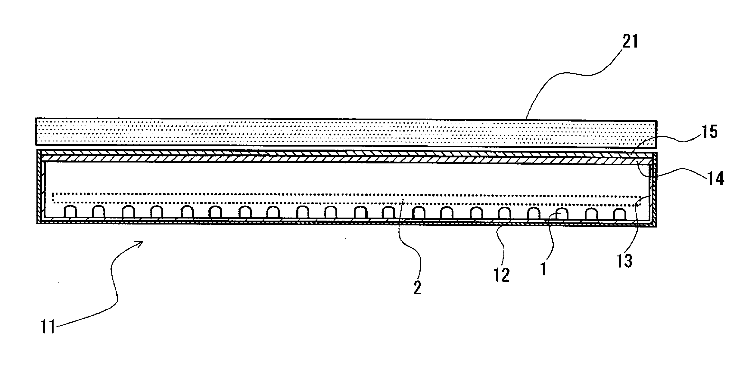
[0114]Moreover, a diffusing sheet (polycarbonate, product name: PC9391-50HL manufactured by TEIJIN CHEMICALS LTD.) was fixed to the front face of the opening portion of the aluminum chassis to fabricate a planar light source device corresponding to FIGS. 3-D and 4.

[0115]For the flat light source device, a current of 220 mA was applied to the series line of four LEDs over which the red color luminescent area and the green color luminescent area were formed, a current of 60 mA was applied to the series line of three LEDs over which ...


PUM

PropertyMeasurementUnit
radiation peak wavelengthaaaaaaaaaa

Abstract

A light guide member, a flat light source device and a display device using the light guide member, by which a white light having a high color rendering property can be obtained without using luminescent devices of a plurality of colors are provided.
A plurality of luminescent devices that emit a light of a violet to blue color are arrayed on a substrate, and a light guide member is disposed upward thereof that includes a first area that consists of a transparent resin and composed of the resin independently, a second area in which there is dissolved in the resin a luminescent substance that generates a second color having a radiation peak wavelength at a wavelength different from a radiation peak wavelength of a luminescent device of the first color by an excitation due to a light emitted from the luminescent device of the first color, and a third area in which there is dissolved in the resin a luminescent substance that generates a third color having a radiation peak wavelength at a wavelength different from the radiation peak wavelengths of luminescent devices of the first and second colors by an excitation due to a light emitted from the luminescent device of the first color.

Description

CROSS REFERENCES OF RELATED APPLICATION[0001]This application is an application filed under 35 U.S.C. §111(a) claiming benefit pursuant to 35 U.S.C. §119(e)(1) of the filing date of Provisional Application 60 / 755,792 filed on Jan. 4, 2006 pursuant to 35 U.S.C. §111(b).TECHNICAL FIELD[0002]The present invention relates to a light guide member for a flat light source device, a flat light source device using the light guide member, and a display device provided with the flat light source device that are used as a back light for a liquid crystal display for instance.BACKGROUND OF THE INVENTION[0003]In recent years, a light emission efficiency of a light-emitting diode device has been extremely improved, and an application of the light-emitting diode device to an illumination is being progressed. In particular, in the case in which there is used a light emitting diode device as a back light for a liquid crystal display, a satisfactory gamut of reproducible colors and a high speed respons...

Claims


Application Information

Patent Timeline
Patent Type & Authority Applications(United States)
IPC IPC(8): G02F1/13357G09F13/08F21V9/40
CPCG02B6/0035G02F1/133603G02F2001/133614G02F1/133609G02F1/133606G02B6/0068G02F1/133614H01L25/0753H01L33/504H01L2924/0002H01L2924/00
Inventor NAIJO, SHUICHITOKITA, KOJI
Owner SHOWA DENKO KK
Why Eureka
Try Eureka