Antenna system and method for controlling an antenna pattern of a communication device

a communication device and antenna pattern technology, applied in the direction of pivotable antennas, collapsible antennas, antennas, etc., can solve the problems of reducing the performance of the cpe, rf signal from one or more antennas may be absorbed by the ground plane of the electronic circuit board of the cpe, and non-uniform antennas

Inactive Publication Date: 2009-04-23
MOTOROLA INC
View PDF5 Cites 11 Cited by
  • Summary
  • Abstract
  • Description
  • Claims
  • Application Information

AI Technical Summary

Problems solved by technology

However, the radiation from the RF signal from the one or more antennas may be absorbed by ground planes of electronic circuit boards of the CPEs.
This may result in a non-uniform antenna pattern, consequently, reducing the performance of the CPE.

Method used


Image

  • Antenna system and method for controlling an antenna pattern of a communication device
  • Antenna system and method for controlling an antenna pattern of a communication device
  • Antenna system and method for controlling an antenna pattern of a communication device

Examples


Embodiment Construction

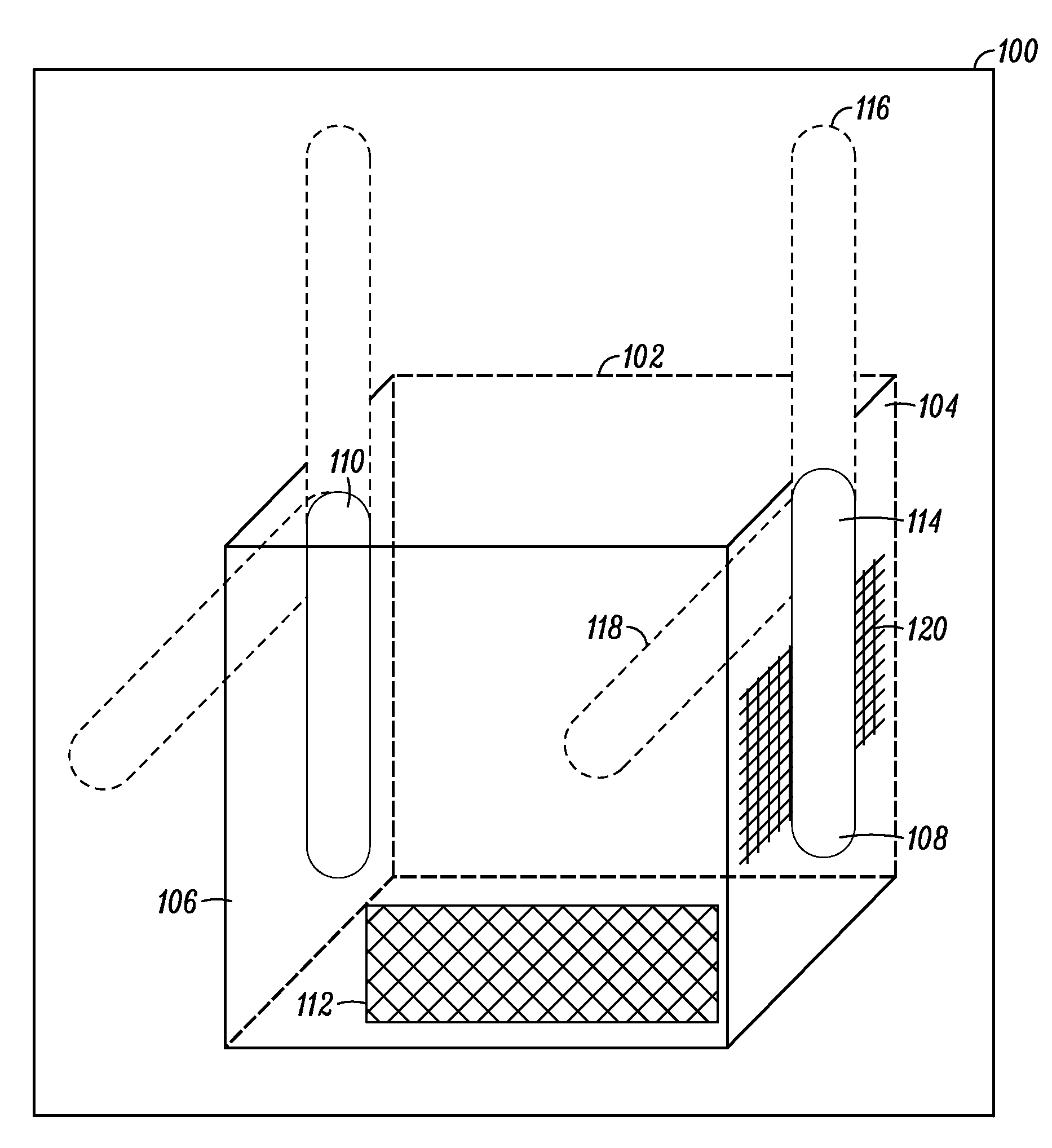
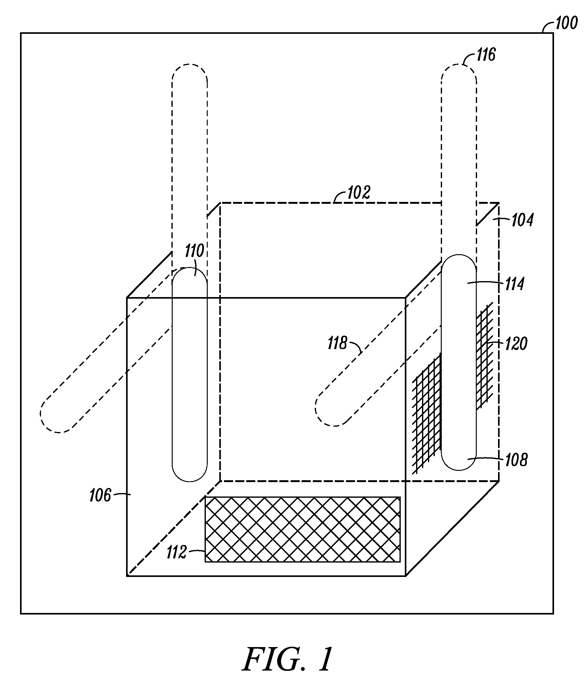
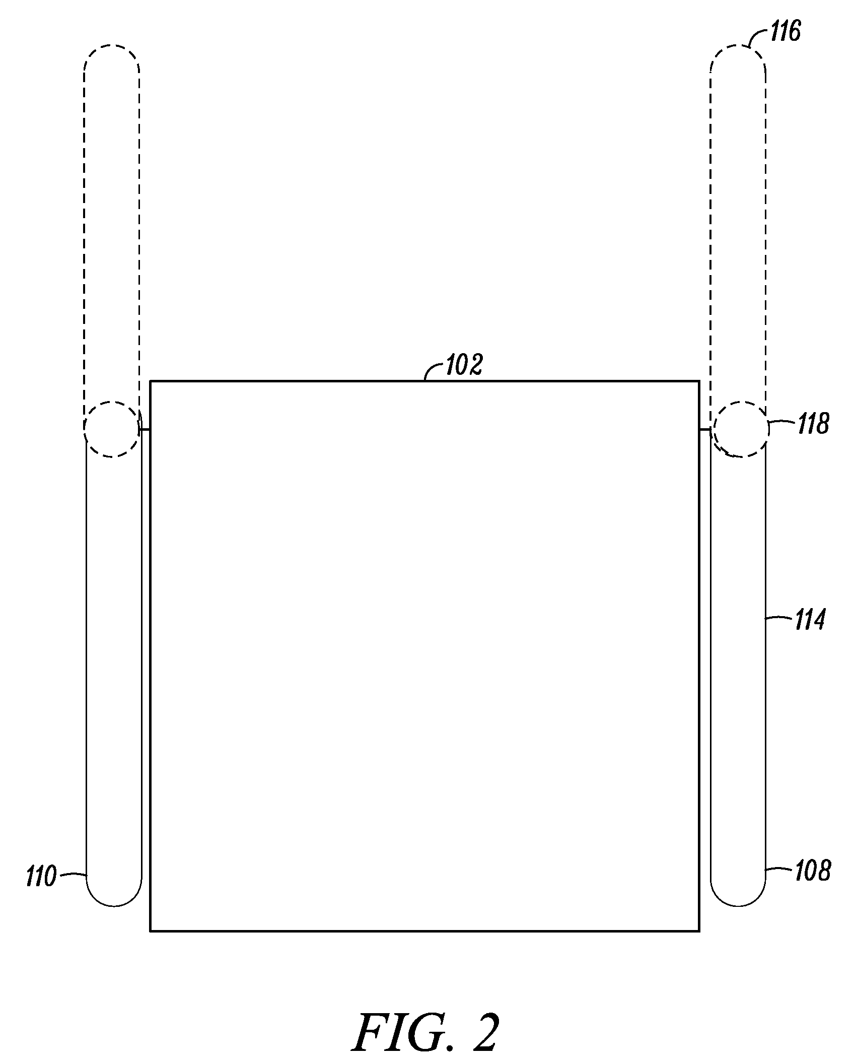
[0013]Before describing in detail embodiments that are in accordance with the present invention, it should be observed that the embodiments reside primarily in combinations of method steps and apparatus components related to an antenna system and method for use within a wireless communication device. Accordingly, the apparatus components and method steps have been represented where appropriate by conventional symbols in the drawings, showing only those specific details that are pertinent to understanding the embodiments of the present invention so as not to obscure the disclosure with details that will be readily apparent to those of ordinary skill in the art having the benefit of the description herein.

[0014]In this document, relational terms such as first and second, top and bottom, and the like may be used solely to distinguish one entity or action from another entity or action without necessarily requiring or implying any actual such relationship or order between such entities o...


PUM


Abstract

The present invention provides an antenna system and method for controlling an antenna pattern in a communication device. The antenna system comprises one or more rotatable antennas and one or more antenna reflectors. The one or more antenna reflectors are electrically isolated reflecting surfaces that are operationally coupled to the one or more rotatable antennas. The method comprises aligning the one or more rotatable antennas in one or more positions with respect to the one or more antenna reflectors so as to provide a repeatable antenna pattern.

Description

FIELD OF THE INVENTION[0001]The present invention generally relates to wireless communication devices, and more specifically, to an antenna system within a wireless communication device.BACKGROUND OF THE INVENTION[0002]Wireless communication systems that utilize radio frequency (RF) signals to transmit and receive data are well known. Wireless data communication can be applied to short distance local area network (LAN) communication systems, such as wireless LAN within a home or office environment. In the case of short distance wireless LAN communication, a wireless access system may include a customer premises equipment (CPE) that is connected to an office or home computer, via an Ethernet interface, for example. Customer-premises equipment or customer-provided equipment (CPE) is any terminal and associated equipment and inside wiring located at a subscriber's premises and connected with a carrier's telecommunication channel(s). CPEs that enable a consumer to connect to the wireles...

Claims


Application Information

Patent Timeline
Patent Type & Authority Applications(United States)
IPC IPC(8): H01Q3/02
CPCH01Q3/02H01Q1/084H01Q1/24
Inventor KANNE, MARK M.RIORDAN, KENNETH B.
Owner MOTOROLA INC
Why Eureka
Try Eureka