Counterforce brace

a technology of anti-force braces and stabilizers, which is applied in the field of stabilizer braces, can solve problems such as “rolling over” of ankles or ankles, arch strain, shin splints, etc., and achieve the effect of resisting excessive pronation or supination

Inactive Publication Date: 2009-04-23
GORDON JR HOWARD A
View PDF24 Cites 21 Cited by
  • Summary
  • Abstract
  • Description
  • Claims
  • Application Information

AI Technical Summary

Benefits of technology

[0010]Another object of the invention is to provide braces, as aforesaid, which present a pair of torque straps and method of wrapping the same so as to present countervailing forces between the metatarsal heads and the superior region of the ankle joint complex which resist excessive pronation or supination.

Problems solved by technology

During excessive supination, the lateral structures of the foot tighten which may rupture or avulse portions of the lateral collateral ligaments resulting in a “rolling over” of the ankle or ankle sprain.
Excessive pronation increases the stress on the inside / medial portion of the foot which may lead to various injuries such as arch strain, heel pain, inner ankle pain and shin splints.
Although assumably effective in their operation, such devices have failed to simultaneously provide the effective stabilization of the ankle and forefoot and in a neutral position.

Method used


Image

  • Counterforce brace
  • Counterforce brace
  • Counterforce brace

Examples


Embodiment Construction

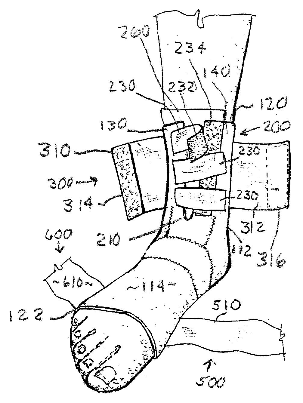
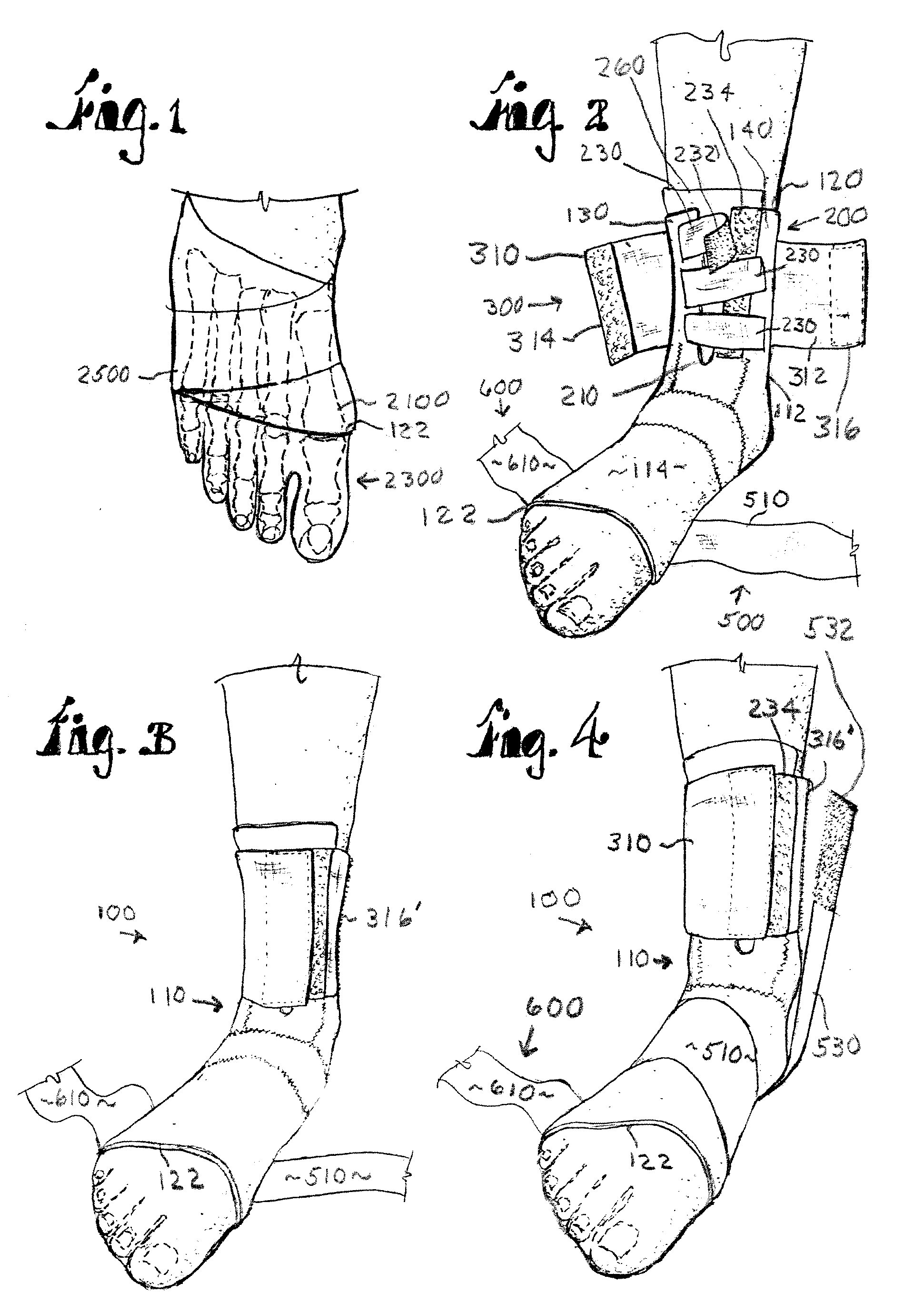
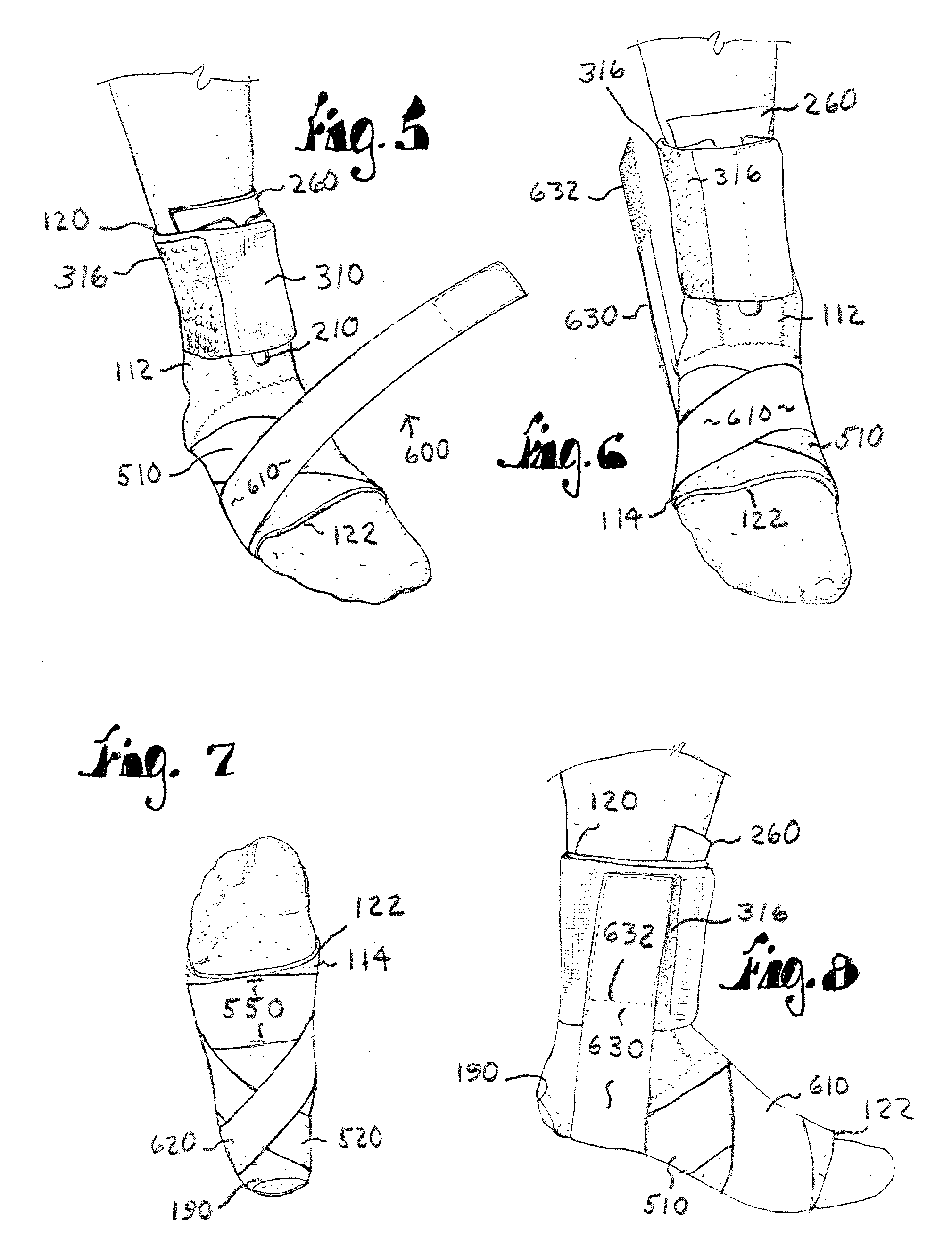
[0046]Turning more particularly to the drawings, the first brace 100 comprises a sock like body 110 made of an elastic material. The body 110 presents first 112 and second 114 integral sleeves made from joined blanks 112′, 114′. The body 110 provides a compression fit about the ankle joint complex and forefoot of the wearer. The forefoot is described as that region of the foot extending from the heel to approximate the distal / head ends of the first 2100 and fifth metatarsals 2500. The body 110 presents a first free edge 120 which circumscribes the foot at a superior position above the ankle joint complex. A second free edge 122 circumscribes the foot adjacent the distal ends / heads of the first 2100 and fifth 2500 metatarsals. It is preferred that this edge 122 not extend beyond such distal ends as it may present discomfort to the foot during flexion. As such, upon slipping the body 110 over the foot, the body 110 presents a compression fit between these edges 120, 122. Portions of t...


PUM


Abstract

A stabilization brace presents a compressive, sock-like body for a compressive fit about the ankle joint and forefoot. A pair of force straps extends from the metatarsal heads and is wound in a preferred manner along opposed regions of the foot and ankle to offer countervailing forces therealong. First and second closure systems secure the body to the foot and offer circumferential support thereto. The brace resists excessive supination and pronation of the foot, ankle joint and underlying structures. Three embodiments of the brace are shown wherein one end of the force straps are attached to a zone adjacent the metatarsals as well as bifurcated ends attached to the metatarsal zone and a second zone spaced therefrom. A third embodiment presents bifurcated ends attached at one zone adjacent the metatarsals and another zone of the rear of the Achilles which presents an enhanced heel locking mechanism.

Description

[0001]This application is a continuation-in-part of application Ser. No. 11 / 709,424, filed Feb. 27, 2007, which is a continuation-in-part of application Ser. No. 11 / 079,942, filed Mar. 15, 2005.BACKGROUND OF THE INVENTION[0002]This invention relates to stabilization braces and more particularly to a support design which stabilizes the ankle and forefoot of the user at a desired neutral position.[0003]The supination of a foot combines inward rotation at the ankle, adduction of the hind foot inversion of the forefoot and medial arch elevation. Basically, supination produces a medial (inward) movement at the talocalcaneal (subtalus) joint known as inversion as well as similar movement between the hind foot (talus) and mid foot (navicular) bones. A foot that supinates appears to naturally favor the lateral region or outside edge of the foot. A certain amount of supination is normal during the toe off stage of running, i.e., when the heel first lifts off the ground until the end of the s...

Claims


Application Information

Patent Timeline
Patent Type & Authority Applications(United States)
IPC IPC(8): A61F5/00A61B19/00
CPCA61F13/066A61F5/0111
Inventor GORDON, JR., HOWARD A.
Owner GORDON JR HOWARD A
Why Eureka
Try Eureka